Portable stirring device
A mixing device and portable technology, applied in the field of portable mixing devices, can solve the problems of high construction power requirements, inconvenient small space, difficult maintenance and cleaning, etc., and achieve the effect of ingenious structure, compact structure and easy operation
- Summary
- Abstract
- Description
- Claims
- Application Information
AI Technical Summary
Problems solved by technology
Method used
Image

Examples
Embodiment 1
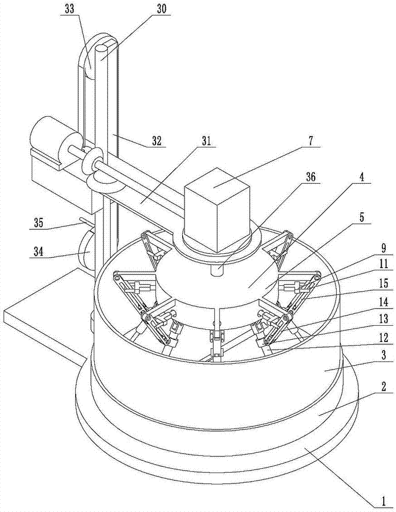
[0034] Embodiment 1, the present invention is a portable stirring device, which is characterized in that it includes a chassis 1, the chassis 1 is a flat steel plate, a plurality of wheels can be installed under the chassis 1, which is convenient to move, and a disc 2 is installed on the chassis 1 , the disc 2 can rotate horizontally, the disc 2 is equipped with a stirring pot 3, the stirring pot 3 is a cylindrical container with an upper end opening, the stirring pot 3 and the disc 2 can be quickly disassembled, and the stirring pot 3 is equipped with a stirring device 4. The concrete is uniformly mixed in the stirring pot 3 under the action of the stirring device 4, and the stirring device 4 is equipped with a fixing device 401, and the fixing device 401 is used to fix the stirring device 4;
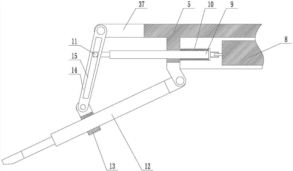
[0035] Described stirring device 4 comprises stirring frame 5, and stirring frame 5 is the shell of lower end opening, and central axis 6 is installed in stirring frame 5 central positi...
Embodiment 2
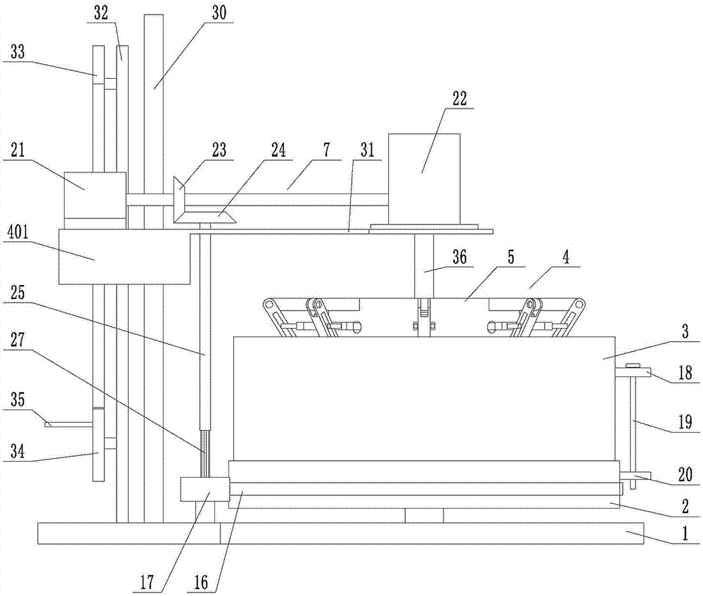
[0037] Embodiment 2, on the basis of Embodiment 1, the outside of the stirring pot 3 is welded with a first protrusion 18, and the first protrusion 18 is pierced with a vertically placed clamping shaft 19, and the clamping shaft 19 is installed with The second protrusion 20 is welded on the disc, and the clamp shaft 19 passes through the first protrusion 18 and the second protrusion 20 sequentially from top to bottom.
Embodiment 3
[0038] Embodiment three, on the basis of embodiment one, described power unit 7 comprises motor 21, is connected reduction box 22 on motor 21, is the worm and gear mechanism in reduction box 22, and reduction box 22 drives central shaft 6 to rotate, and motor 21 The first bevel gear 23 is installed between the reduction box 22, the motor 21 drives the first bevel gear 23 to rotate, the second bevel gear 24 placed horizontally is engaged with the first bevel gear 23 below, and the second bevel gear 24 lower end is equipped with The spline cylinder 25 is sleeved with a spline shaft 27, the spline cylinder 27 can slide up and down along the spline shaft 25, and the lower end of the spline shaft 27 is fixedly installed with the cylindrical gear.
PUM
 Abstract
Description
Claims
Application Information
 - R&D Engineer
- R&D Manager
- IP Professional
- Industry Leading Data Capabilities
- Powerful AI technology
- Patent DNA Extraction
Browse by: Latest US Patents, China's latest patents, Technical Efficacy Thesaurus, Application Domain, Technology Topic.
© 2024 PatSnap. All rights reserved.Legal|Privacy policy|Modern Slavery Act Transparency Statement|Sitemap