Al technical title is built by PatSnap Al team. It summarizes the technical point description of the patent document.
An injection mold and nut technology, applied in the field of mold applications, can solve the problems of long flow of injection liquid, cracks on the surface of the nut, and low injection quality, and achieve the effect of reducing voids, demoulding cleanly, and reducing the flow path.
Active Publication Date: 2019-10-15
漳州盈新精密模具有限公司
View PDF1 Cites 0 Cited by
Summary
Abstract
Description
Claims
Application Information
AI Technical Summary
This helps you quickly interpret patents by identifying the three key elements:
Problems solved by technology
Method used
Benefits of technology
Problems solved by technology
[0003] Nuts are mostly formed by injection molding during production. Most of the existing nut injection molds are injected from the upper template to the inside of the lower template. The injection molding liquid in this injection molding method has a long path, and it is easy to cause the injection molding liquid to solidify inside the channel. The channel is blocked, and at the same time, manual mold opening and closing will cause cracks on the surface of the nut when there is a slight shake, resulting in low production speed and low injection quality.
Method used
Image
Click on the blue label to locate the original text in one second.
Reading with bidirectional positioning of images and text.
Examples
Embodiment Construction
[0022] The following will clearly and completely describe the technical solutions in the embodiments of the present invention with reference to the accompanying drawings in the embodiments of the present invention. Obviously, the described embodiments are only some, not all, embodiments of the present invention. Based on the embodiments of the present invention, all other embodiments obtained by persons of ordinary skill in the art without making creative efforts belong to the protection scope of the present invention.
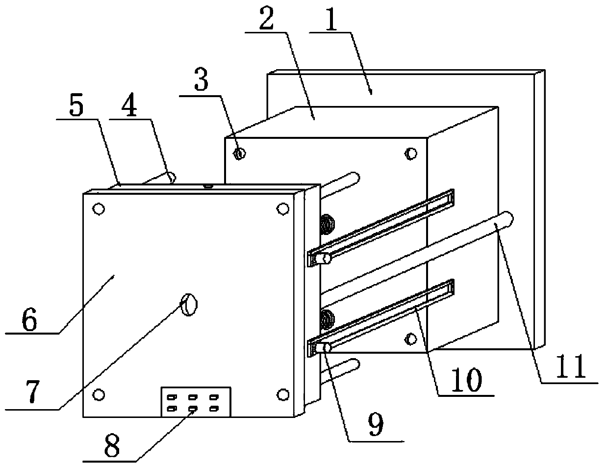
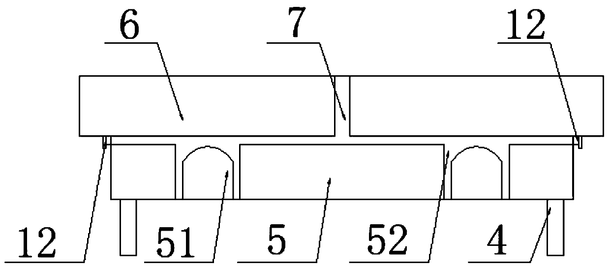
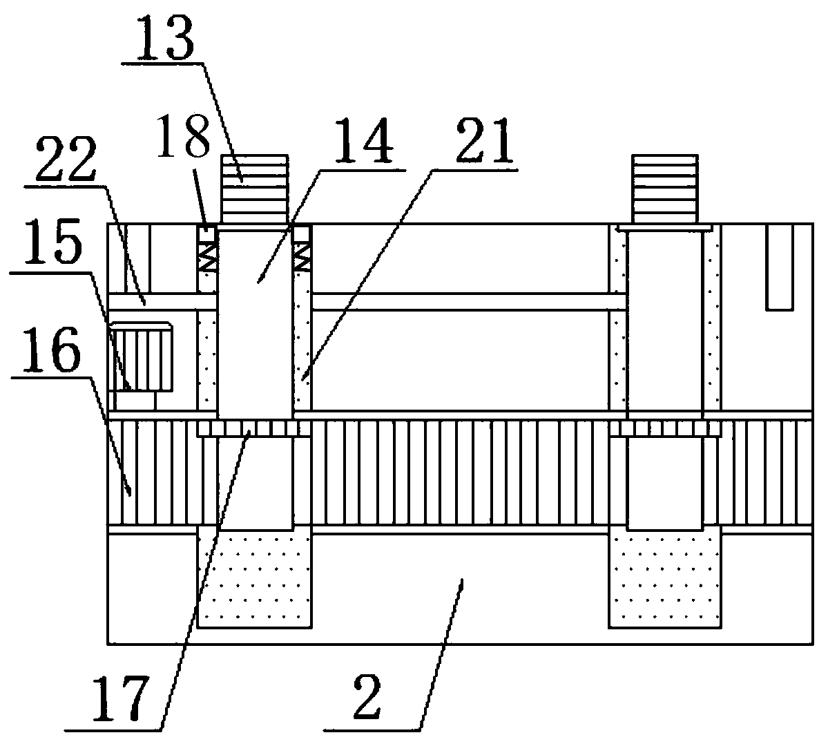
[0023] see Figure 1-4 Shown, a kind of screw cap injection mold comprises upper template 5 and lower template 2, and the bottom bolt of described lower template 2 is equipped with base plate 1, and described lower template 2 is provided with two cavities 21 inside; A connecting rod 14 is arranged inside the cavity 21 , and one end of the connecting rod 14 is connected to the screw rod 13 .
[0024] The upper end surface of the lower template 2 is provided wi...
PUM
Abstract
The invention discloses a nut injection mold. The nut injection mold comprises a bottom plate, a lower mold plate, a cavity, an injection liquid inlet, a positioning hole, a positioning column, an upper mold plate, a mold cavity, a cooling water channel, a top plate, a water outlet, a button, a stand column, a limiting plate, an electric pushing rod, a water inlet, a threaded rod, a connecting rod, an injection liquid channel, an electric heating wire, a motor, a rack band, a gear and a baffle. The nut injection mold has the beneficial effects that the two mold plates can be opened during automatic mold assembly and demolding, steadiness and rapidness are achieved, the phenomena that nuts are deformed and cracked due to collision during demolding are eliminated, the injection speed is increased, and the injection quality is improved; and meanwhile, injection molding is conducted by spraying injection liquid at the top of the threaded rod, on the one hand, the flowing distance of the injection liquid is reduced, through cooperation with the electric heating wire, solidification of the injection liquid at the channel is prevented, holes formed during injection are reduced, demolding is conducted through ascending and descending of the threaded rod driven by the gear in an electric mode, automatic demolding is achieved, and demolding is clean and stable.
Description
technical field [0001] The invention relates to an injection mold, in particular to a screw cap injection mold, which belongs to the technical field of mold application. Background technique [0002] A nut is a part that is screwed together with a bolt or a screw for fastening. It is an element that must be used in all manufacturing machinery. According to different materials, the inside of the nut adopts a threaded structure, and through the rotation between the bolt and the screw The upper and lower position changes to control the tightness of the connection. Although the nut has a simple structure, it is an indispensable and important part in many industries. [0003] Nuts are mostly formed by injection molding during production. Most of the existing nut injection molds are injected from the upper template to the inside of the lower template. In this injection molding method, the injection liquid flows through a long distance, and it is easy to cause the injection liquid ...
Claims
Application Information
Patent Timeline
Application Date:The date an application was filed.
Publication Date:The date a patent or application was officially published.
First Publication Date:The earliest publication date of a patent with the same application number.
Issue Date:Publication date of the patent grant document.
PCT Entry Date:The Entry date of PCT National Phase.
Estimated Expiry Date:The statutory expiry date of a patent right according to the Patent Law, and it is the longest term of protection that the patent right can achieve without the termination of the patent right due to other reasons(Term extension factor has been taken into account ).
Invalid Date:Actual expiry date is based on effective date or publication date of legal transaction data of invalid patent.