Electric power storage device of new energy automobile

A technology of new energy vehicles and power storage devices, which is applied in the direction of electric power devices, power devices, vehicle components, etc. It can solve problems such as shortened service life, damage to power storage parts, and vehicle exhaust pollution, so as to prevent swinging and enhance firmness , The effect of quick lock installation

Inactive Publication Date: 2017-11-07
广州市灵汐科技有限公司
View PDF0 Cites 16 Cited by
  • Summary
  • Abstract
  • Description
  • Claims
  • Application Information

AI Technical Summary

Problems solved by technology

[0002] In recent years, the problem of urban environmental pollution has become more and more serious, among which automobile exhaust pollution is increasingly endangering people's health. With the improvement of environmental awareness, the rapid development of low-carbon economy and energy-saving and emission-reduction technologies, new energy electric vehicles Its non-polluting advantages have begun to be widely used in daily life. New energy electric vehicles use a single battery as the energy storage power source. The battery provides electric energy to the motor to drive the car. The battery is used as a new energy electric vehicle. The core technology of new energy electric vehicles, the stability after installation and the simplicity of repair and maintenance after failure are urgent problems for new energy electric vehicles. The storage parts of existing new energy electric vehicles are generally fastened by bolts In the engine room, however, the bolt fastening method will not only cause damage to the power storage parts due to excessive bolt tightening force and shorten the service life, but also need to use screwdrivers and other disassembly tools to disassemble the power storage parts after failure. The installation and disassembly process is too cumbersome and complicated, time-consuming and labor-intensive, which seriously affects the efficiency of maintenance

Method used


Image

  • Electric power storage device of new energy automobile
  • Electric power storage device of new energy automobile
  • Electric power storage device of new energy automobile

Examples


Embodiment Construction

[0021] All features disclosed in this specification, or steps in all methods or processes disclosed, may be combined in any manner, except for mutually exclusive features and / or steps.

[0022] Any feature disclosed in this specification (including any appended claims, abstract and drawings), unless expressly stated otherwise, may be replaced by alternative features which are equivalent or serve a similar purpose. That is, unless expressly stated otherwise, each feature is one example only of a series of equivalent or similar features.

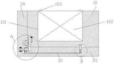
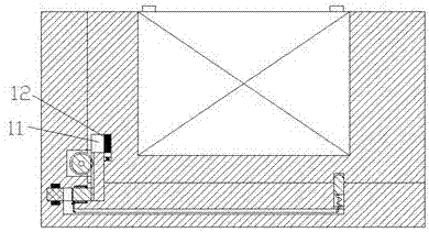
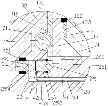
[0023] Such as Figure 1-6 As shown, a new energy vehicle power storage device of the present invention includes a carrier plate 20 fixed in the engine room of the vehicle and a mounting frame 10 for installing the battery, and the mounting frame 10 is provided with a cavity with the mouth facing upwards. 101, a storage battery 102 is installed in the cavity 101, and the top of the storage battery 102 is equipped with a handle 103 on the left...


PUM


Abstract

A power storage device for a new energy vehicle, including a load plate fixed in the engine room of the vehicle and a mounting frame for installing the battery. The mounting frame is provided with a cavity with the mouth facing upward, and the battery can be lifted and placed in the cavity. , the top of the battery is equipped with handles on the left and right, the left end of the bearing plate is fixed with an upwardly extending vertical plate, and the lower end of the vertical plate is provided with a placement groove with the mouth facing right, and a toothed wheel is rotatably installed in the placement groove , the toothed wheel is driven by a motor fixedly installed in the vertical plate, the toothed wheel penetrates the placement groove, the left end of the mounting frame is provided with a first sliding groove with the mouth facing downward, and a sliding groove is installed in the first sliding groove Moving plate, the left end surface of the sliding plate is provided with a toothed bar, the left end wall of the first sliding groove is provided with a communication groove, the loading plate is provided with a fastening groove opposite to the first sliding groove, and the left end of the fastening groove is also provided with a Second slip slot.

Description

technical field [0001] The invention relates to the technical field of new energy vehicles, in particular to a power storage device for new energy vehicles. Background technique [0002] In recent years, the problem of urban environmental pollution has become more and more serious, among which automobile exhaust pollution is increasingly endangering people's health. With the improvement of environmental awareness, the rapid development of low-carbon economy and energy-saving and emission-reduction technologies, new energy electric vehicles Its non-polluting advantages have begun to be widely used in daily life. New energy electric vehicles use a single battery as the energy storage power source. The battery provides electric energy to the motor to drive the car. The battery is used as a new energy electric vehicle. The core technology of new energy electric vehicles, the stability after installation and the simplicity of repair and maintenance after failure are urgent proble...

Claims


Application Information

Patent Timeline
Patent Type & Authority Applications(China)
IPC IPC(8): B60K1/04
CPCB60K1/04B60K2001/0494
Inventor 叶翠颖
Owner 广州市灵汐科技有限公司
Why Eureka
Try Eureka