Electric vehicle thermal management system

A thermal management system and electric vehicle technology, applied in the field of electric vehicles, can solve problems such as complex system control strategies, complex thermal management design, and low reliability, and achieve the goal of avoiding control logic and diagnosis, simple structure, and convenient maintenance and management Effect

A thermal management system and electric vehicle technology, applied in the field of electric vehicles, can solve problems such as complex system control strategies, complex thermal management design, and low reliability, and achieve the goal of avoiding control logic and diagnosis, simple structure, and convenient maintenance and management Effect

CN107323285AActive Publication Date: 2017-11-07奇瑞新能源汽车股份有限公司

Image

  • Electric vehicle thermal management system

Examples


Embodiment Construction

[0052] In order to make the technical solutions and advantages of the present invention clearer, the embodiments of the present invention will be further described in detail below in conjunction with the accompanying drawings.

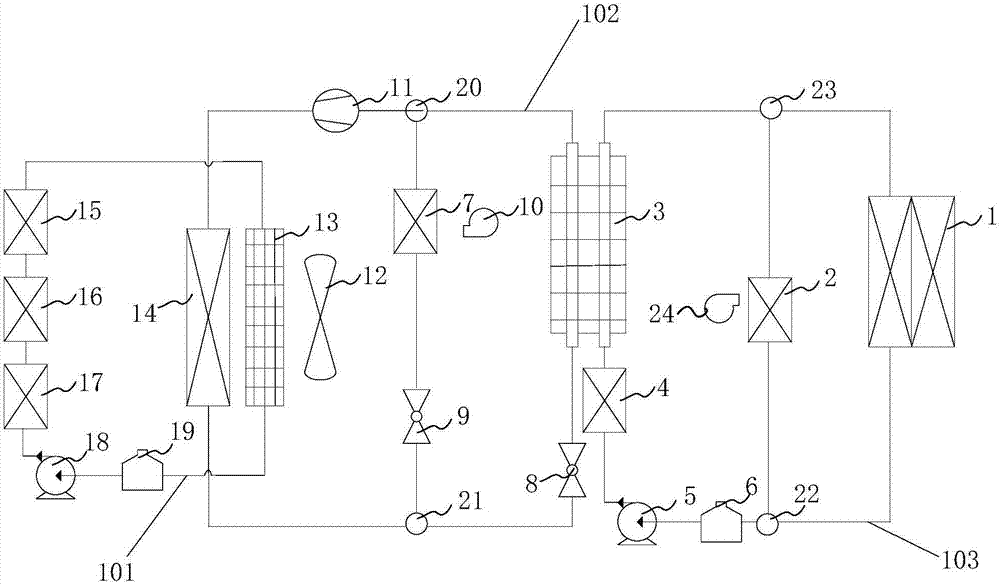
[0053] An embodiment of the present invention provides a thermal management system for an electric vehicle, the structural diagram of which is shown in figure 1 As shown, it includes an electric drive cooling circuit 101 , an air conditioning circuit 102 and a battery thermal management circuit 103 .

[0054] The electric drive cooling circuit 101 passes through the electric drive device and is suitable for thermal management of the electric drive device. The electric drive cooling circuit 101 is provided with a radiator 13 and a first water pump 18 to cool the electric drive device.

[0055] The air conditioning circuit 102 is provided with a condenser 14 and a compressor 11 , and includes an evaporation branch provided with an evaporator 7 , and a he...


PUM


Abstract

The invention discloses an electric vehicle thermal management system, and belongs to the field of electric vehicles. The electric vehicle thermal management system comprises an electrically-driven cooling circuit, an air conditioning circuit and a battery thermal management circuit. A heat exchanger is connected to a main branch of the battery thermal management circuit and a heat exchanging branch in the air conditioning circuit so that the air conditioning circuit and the battery thermal management circuit can achieve heat exchanging; whether a vehicle is driven or charged, heat in the electric vehicle thermal management system can be distributed, and unified thermal management of an electric driving device, an air conditioner and a battery device is achieved; and meanwhile the electric vehicle thermal management system reduces the components of a water valve, a tee joint and the like, the structure is simple, complex control logic and diagnosis are avoided, and therefore the later maintenance and management are more convenient.

Description

technical field [0001] The invention relates to the field of electric vehicles, in particular to a heat management system for electric vehicles. Background technique [0002] In order to avoid damage caused by overheating of components caused by the accumulation of heat energy in the electric vehicle, and to provide a comfortable temperature in the cabin, it is necessary to dissipate heat from the operating components and transfer the heat energy of the vehicle air conditioner. Therefore, how to manage the heat energy distribution of electric vehicles is the current vehicle research. one of the directions. [0003] The electric vehicle thermal management system in the prior art includes a power cooling unit, a heating and cooling air-conditioning unit, a heat exchange unit and a control unit. The heat exchange path is controlled and adjusted by the control unit to adjust the flow rate of the coolant in the power cooling unit, so that the heat dissipation capacity of the pow...

Claims


Application Information

Patent Timeline
07 Nov 2017
Publication
CN107323285A
IPC
B60L11/18; B60K1/00; B60H1/00
CPC
B60H1/00278; B60H1/00735; B60K1/00; B60K2001/005; B60K2001/006; B60L2240/545; B60L58/26; B60L58/27
Inventors
吴亚东; 倪绍勇