
Air pressure brake type hydraulic coupling hose or cable coiling block

A technology of air pressure braking and cable reel, which is applied in the field of hose or cable reel, which can solve the problems of large anti-pull force, complicated control, and inconvenient adjustment, etc., and achieve stable and accurate air pressure braking, soft mechanical properties, and easy conversion smooth and simple effect

Pending Publication Date: 2017-11-07
YUEYANG HAIRUN ELECTRIC
View PDF4 Cites 2 Cited by
  • Summary
  • Abstract
  • Description
  • Claims
  • Application Information

AI Technical Summary

Problems solved by technology

In addition, the hydraulic coupling can only transmit the input torque to the output device unchanged.
Due to the above characteristics, the speed and winding force of the hose or cable reel driven by the hydraulic coupling are not easy to control and adjust during the process of retracting the hose or cable. impact tension failure
[0003] The hose or cable reel driven by frequency conversion needs to customize the frequency converter, and the control is complicated, especially for the working conditions with large moment of inertia, high acceleration and fast speed, which cannot meet this requirement very well
And due to acceleration requirements, in terms of response speed, frequency conversion speed regulation reels usually have to reduce energy efficiency, which can only be solved by using a large horse-drawn cart, which cannot effectively protect hoses or cables
[0004] Hose or cable reels driven by hysteresis coupling, due to the high back-pull force when laying down the tube or cable, the hose or cable is prone to injury
In addition, the torque provided by the hysteresis coupler must be controlled by adjusting the air gap between the induction disc of the hysteresis coupler and the disk, and the adjustment is not very convenient.

Method used


Image

  • Air pressure brake type hydraulic coupling hose or cable coiling block
  • Air pressure brake type hydraulic coupling hose or cable coiling block
  • Air pressure brake type hydraulic coupling hose or cable coiling block

Examples


Embodiment Construction

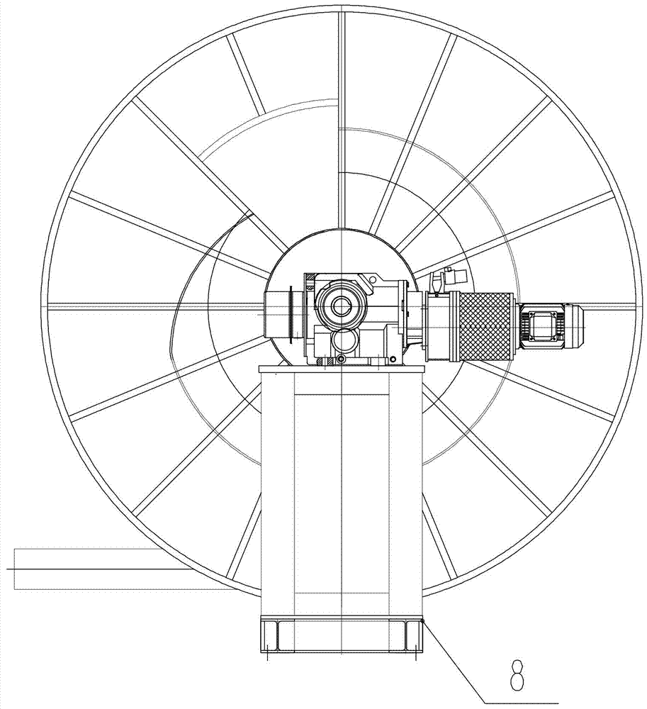
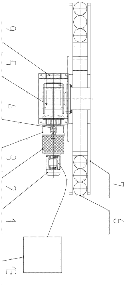
[0021] from Figures 1~3 It can be seen that the present invention is a pneumatic brake hydraulic coupling drive hose or cable reel, including a drive motor 1, a hydraulic coupling 2, a pneumatic brake 3, a connection mount 4, a reduction box 5, a hose or a cable reel 7. Connecting shaft 10 , transition plate 11 , transition plate 12 , electrical control box 13 . The hydraulic coupling 2 is connected to the driving motor 1 through a rigid coupling, and the electric control box 13 controls the forward and reverse rotation of the driving motor 1, thereby driving the hydraulic coupling 2 to rotate. The transition plates 11 and 12 are respectively connected with the driving motor 1 and the reduction box 5 , and the two ends of the connecting shaft 10 are respectively connected with the output shaft of the driving motor 1 and the main shaft of the reduction box 2 . In the present invention, an installation support 8 can be added under the base of the reduction box 5, and the struc...


PUM


Abstract

The invention discloses an air pressure brake type hydraulic coupling driving hose or cable coiling block. A hydraulic coupler is connected with a drive motor through a rigidity coupler. The drive motor is controlled by an electrical control box to rotate forwards and reversely and drives the hydraulic coupler to rotate. A transition plate is connected with the drive motor and the speed reduction box, and the two ends of a connecting shaft are connected with an output shaft of the drive motor and a main shaft of the speed reduction box correspondingly. A brake frame of an air pressure brake is arranged on a connecting installing base through a fixing pin, and the main shaft of the speed reduction box is in rigidity connection with a reel. According to the air pressure brake type hydraulic coupling driving hose or cable coiling block, air pressure brake type hydraulic coupling is adopted for driving the hose or the cable, the speed of hose or cable winding and unwinding through the reel is adjustable, the winding and unwinding speed and the tension of the hose or the cable can be easily and conveniently adjusted in the hose or cable winding and unwinding process, and the hose or the cable can be more effectively protected.

Description

technical field [0001] The invention relates to a mobile energy supply device, in particular to a hose or cable reel driven by a pneumatic brake hydraulic coupling. technical background [0002] At present, the hose or cable reel is mainly driven by several forms of hydraulic coupling, variable frequency drive or hysteresis coupling. The above various driving forms have their own advantages and disadvantages, which are described as follows: the hose or cable reel driven by the hydraulic coupling, through the flexible driving system composed of the high-slip hydraulic coupling and the electrical controller, is relatively It solves the problems of high frequency, high speed and high reliability of retracting and releasing hoses or cables. However, because the hydraulic coupling is rotated by the high-speed liquid, the coupling turbine is subjected to the impact force of the hydraulic oil, so the hydraulic coupling hose or cable reel needs to maintain a fast retracting speed, ...

Claims


Application Information

Patent Timeline
IPC IPC(8): B65H75/44
CPCB65H75/4442B65H75/4486B65H2701/34B65H2701/33
Inventor 刘剑杨大林刘彬陈世华符建光
Owner YUEYANG HAIRUN ELECTRIC
Learn More