Municipal road structure by river under overpass

A technology for road structures and viaducts, applied in bridges, bridge parts, bridge construction, etc., can solve problems such as prone to inclination, affecting project progress, and inability to cut off water flow, etc., to achieve increased firmness, low density, improved construction convenience and speed effect

Inactive Publication Date: 2017-11-07
泉州圆创机械技术开发有限公司
View PDF1 Cites 6 Cited by
  • Summary
  • Abstract
  • Description
  • Claims
  • Application Information

AI Technical Summary

Problems solved by technology

[0005] Aiming at the deficiencies in the prior art, the purpose of the present invention is to provide a municipal road structure facing the river under the viaduct, so as to solve the problem that the bridge pier in the prior art cannot resist the impact force, and it is prone to inclination under the impact of long-term water flow, and the side construction When pouring with changing sides, the water flow cannot be cut off, and it is vulnerable to impact, which affects the progress of the project

Method used


Image

  • Municipal road structure by river under overpass
  • Municipal road structure by river under overpass
  • Municipal road structure by river under overpass

Examples


Embodiment 1

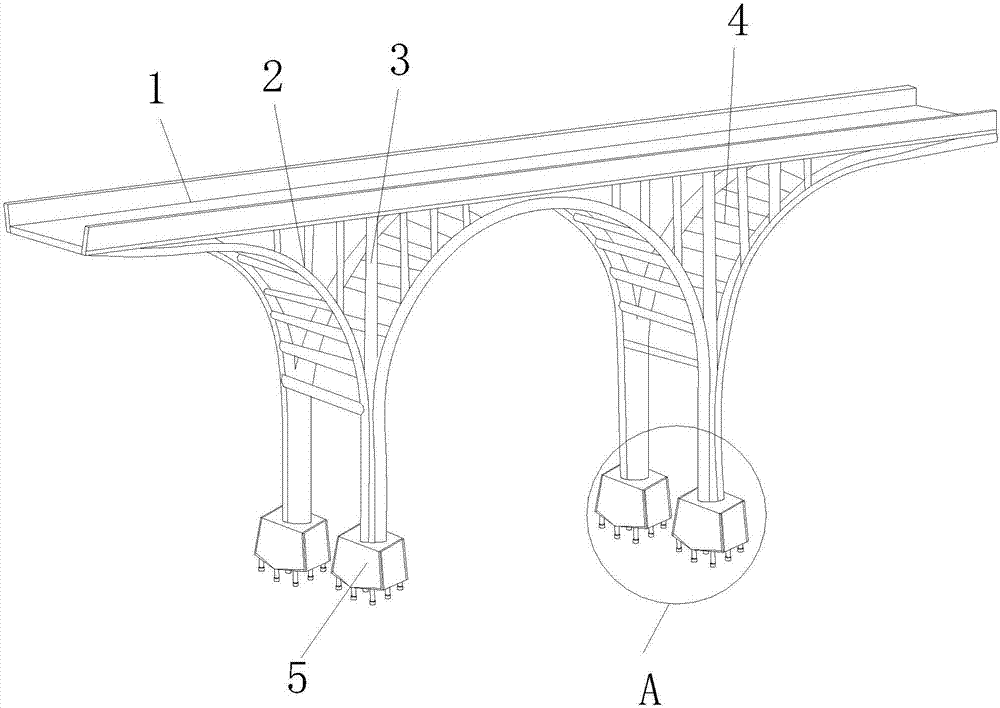
[0041] see Figure 1-Figure 11 , the present invention provides a municipal road structure next to the river under the viaduct. The arc-shaped support rods 2 above the root are fixed together with the pier 5, and the horizontal bars 4 and = are welded between the two parallel arc-shaped support rods 2. One end of the vertical connecting rod 3 is embedded in the road surface of the viaduct. 1, the other end of the vertical connecting rod 3 is welded to the top surface of the arc support rod 2 .

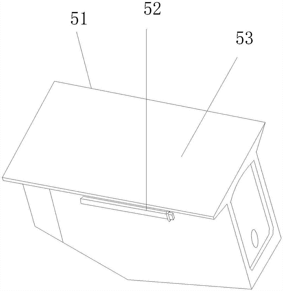
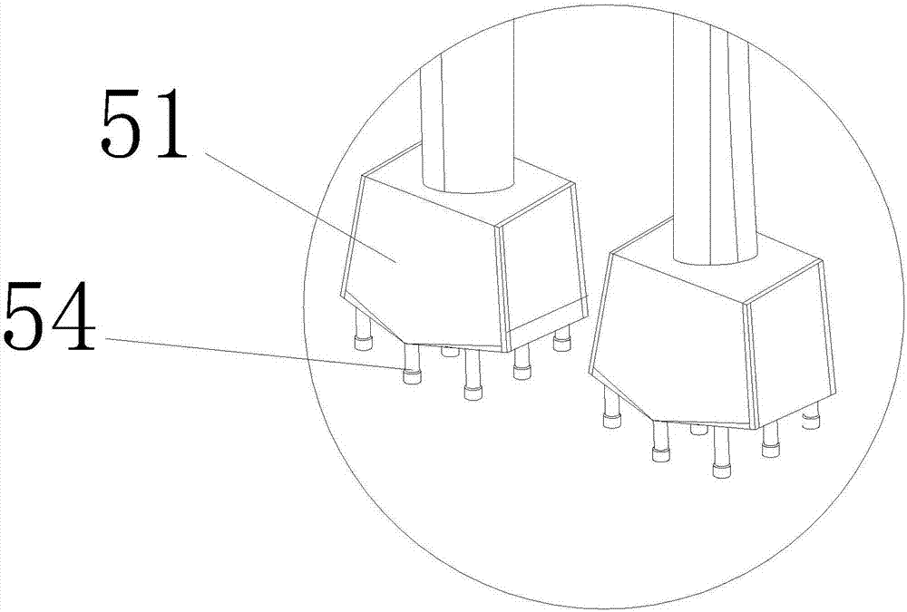
[0042] The pier 5 consists of an outer shell 51, a hanger 52, an internal support mechanism 53, and a sinking fixing device 54. The front side of the outer shell 51 is provided with a hanger 52, and the internal support mechanism 53 is located on its bottom surface. The sinking fixing device 54 is wound together by a wire rope, and the internal support mechanism 53 is arranged inside the outer casing 51 .

[0043] The internal support mechanism 53 is provided with an anti-shock verti...

Embodiment 2

[0050] see Figure 1-Figure 13 The sagging fixing device 54 of the present invention is composed of a bottom fixing panel 541, a lower post 542, and a contact post 543. The lower post 542 is provided with two groups of three, and the lower post 542 and The contact column 543 is an integral molding structure of the mold. The lower insertion column 542 penetrates the mounting hole on the fixed panel 541 from top to bottom. The lower insertion column 542 is provided with a first pouring cavity 5421 and anchor ribs 5422 inside. , the second pouring cavity 5422, the reinforcing rib 5424, the described one is provided with two anchoring ribs 5422 and the two are fixed together by more than two reinforcing ribs 5424, the gap between the reinforcing ribs 5424 and the anchoring ribs 5422 The formed diamond-shaped space is the second pouring cavity 5422 , the first pouring cavity 5421 is located on both sides of the anchor rib 5422 , and the first pouring cavity 5421 and the second pour...


PUM


Abstract

The invention discloses a riverside municipal road structure under a viaduct, which comprises a viaduct upper road surface, arc-shaped support rods, vertical connecting rods, horizontal cross bars, and bridge piers, and the viaduct upper road surface is supported by more than two arc-shaped The rod and the pier are fixed together, and the two arc-shaped support rods parallel to the front and rear are welded with horizontal bars, and one end of the vertical connecting rod is embedded in the road surface of the viaduct, and the vertical connection The other end of the rod is welded to the top surface of the arc-shaped support rod, and there are structures such as a sinking fixing device, an anti-shock vertical plate, a concrete filling device, a first support stand, and a second support stand to improve the impact resistance of the water flow of the present invention. It will not be skewed due to the impact of water flow over time. It is integrated with concrete pouring, which has low density and increased firmness. Improve construction convenience and speed.

Description

technical field [0001] The invention relates to a riverside municipal road structure under a viaduct, which belongs to the field of municipal engineering. Background technique [0002] Viaduct refers to a bridge resting on a series of narrow reinforced concrete or masonry arches, with high supporting towers or pillars, across valleys, rivers, roads or other low obstacles. After urban development, traffic congestion, dense buildings, However, it is difficult to widen the streets. Using this kind of bridge can evacuate traffic density and improve transportation efficiency. In addition, in order to avoid intersecting with other lines, save land, and reduce subsidence of the roadbed, embankments may not be used on expressways or railways between cities. With this kind of bridge, due to the restrictions of existing buildings and the requirements of the line, every curved bridge and sloping bridge can use a slab structure for the sake of beauty. The thickness of the slab can be co...

Claims


Application Information

Patent Timeline
Patent Type & Authority Applications(China)
IPC IPC(8): E01D19/02E01D19/00
CPCE01D19/02E01D19/00
Inventor 谢晓燕黄佳鑫林福清林志鹏
Owner 泉州圆创机械技术开发有限公司
Why Eureka
Try Eureka