Universal coupler
A technology for universal couplings and coupling parts, which is applied in couplings, elastic couplings, mechanical equipment, etc., can solve the problems of high cost and difficulty in die forging, and achieve low cost and difficulty in processing and manufacturing. low effect
- Summary
- Abstract
- Description
- Claims
- Application Information
AI Technical Summary
Problems solved by technology
Method used
Image

Examples
Embodiment 1
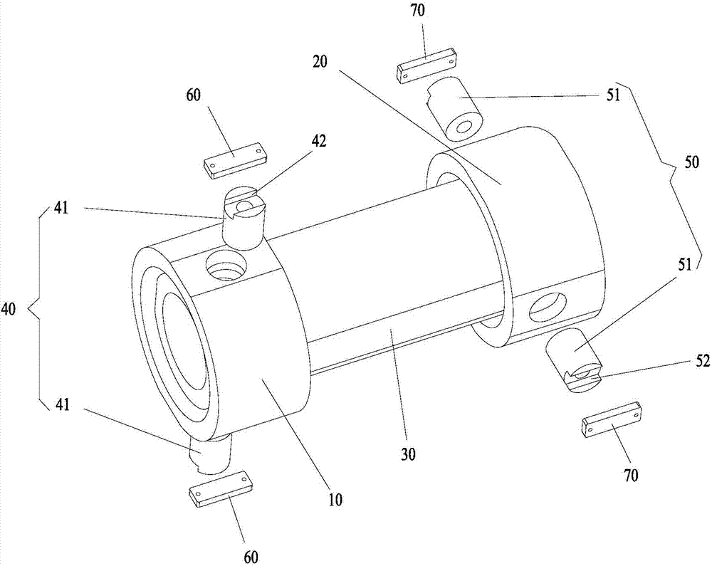
[0028] The universal joint of this embodiment is used to connect the driving shaft and the driven shaft, and transmit the torque from the driving shaft to the driven shaft.
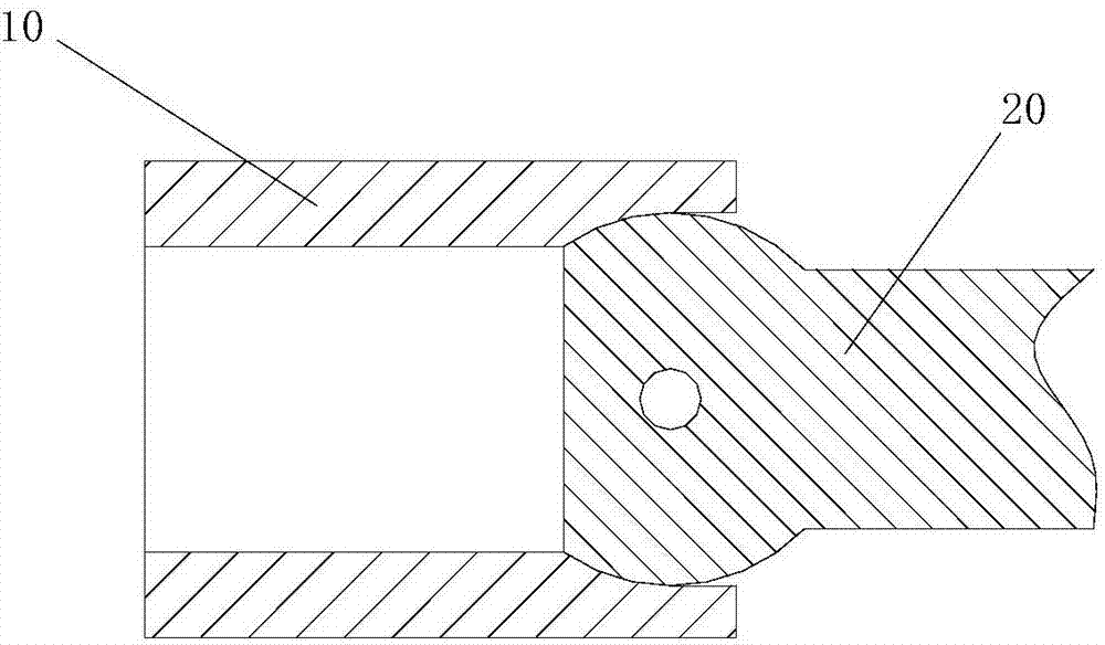
[0029] Such as figure 1 As shown, the universal joint of this embodiment includes a first shaft coupling 10, a second shaft coupling 20, and a first shaft coupling that is rotationally connected to the first shaft coupling 10 and the second shaft coupling 20, respectively. 30. One end of the first shaft coupling 30 in the length direction is rotationally connected to the first shaft coupling 10 through a first rotating shaft 40 . The other end in the length direction of the first shaft coupling 30 is rotationally connected to the second shaft coupling 20 via a second rotating shaft 50 . The first rotating shaft 40 and the second rotating shaft 50 are respectively perpendicular to the length direction of the first coupling 30 , and the first rotating shaft 40 and the second rotating shaft 50 are perpendi...
Embodiment 2
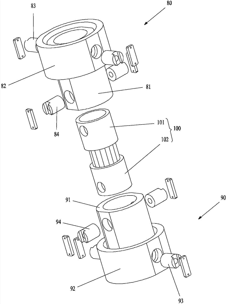
[0049] Such as figure 2 As shown, the universal joint of this embodiment includes a first universal joint 80 , a second universal joint 90 and a mandrel 100 . The first universal joint 80 and the second universal joint 90 are respectively rotatably connected to two opposite ends of the mandrel 100 . The first universal joint 80 and the second universal joint 90 are respectively used for connecting with an external transmission shaft. The axes of the two outer drive shafts are at an angle and still transmit torque so that they rotate together.
[0050] The first universal joint 80 in this embodiment includes a second coupling 81 and a third coupling 82 . One end of the second shaft coupling 81 in the length direction is rotationally connected to the third shaft coupling 82 via a third rotating shaft 83 . The other end in the length direction of the second coupling 81 is rotatably connected to one end of the mandrel 100 through the fourth rotating shaft 84 . The third rotat...
Embodiment 3
[0055] Such as figure 2 As shown, the difference from the second embodiment above is that the second universal joint 90 of this embodiment includes a third coupling joint 91 and a fourth coupling member 92 . One end of the third shaft coupling 91 in the length direction is rotationally connected to the fourth shaft coupling 92 through a fifth rotating shaft 93 . The other end in the length direction of the third coupling 91 is rotatably connected to one end of the spindle 100 through the sixth rotating shaft 94 . The fifth rotating shaft 93 and the sixth rotating shaft 94 are respectively perpendicular to the length direction of the third coupling 91 , and the fifth rotating shaft 93 and the sixth rotating shaft 94 are perpendicular to each other.
[0056] The structure of the third coupling 91 in this embodiment is the same as that of the first coupling 30 in the first embodiment. The structure of the fourth shaft coupling 92 is the same as that of the first shaft coupling...
PUM
 Abstract
Description
Claims
Application Information
 - R&D
- Intellectual Property
- Life Sciences
- Materials
- Tech Scout
- Unparalleled Data Quality
- Higher Quality Content
- 60% Fewer Hallucinations
Browse by: Latest US Patents, China's latest patents, Technical Efficacy Thesaurus, Application Domain, Technology Topic, Popular Technical Reports.
© 2025 PatSnap. All rights reserved.Legal|Privacy policy|Modern Slavery Act Transparency Statement|Sitemap|About US| Contact US: help@patsnap.com