Floating-type gear transmission device

A gear transmission and floating technology, applied in the direction of gear transmission, transmission, transmission parts, etc., can solve the problems of high design requirements and complex design of the base, improve the combination of tooth surfaces, simple ball shoe structure and low cost low effect

Pending Publication Date: 2017-11-07
NANJING XIPU CEMENT ENG GROUP
View PDF5 Cites 3 Cited by
  • Summary
  • Abstract
  • Description
  • Claims
  • Application Information

AI Technical Summary

Problems solved by technology

The second method: add a rubber pad to the gear base to improve the contact of the tooth surface by the deformation of the rubber pad, but this form causes the pinion shaft to swing, and the design requirements for the base are relatively high and the design is complicated

Method used


Image

  • Floating-type gear transmission device
  • Floating-type gear transmission device

Examples


Embodiment Construction

[0015] The present invention will be further illustrated below in conjunction with the accompanying drawings and specific embodiments. This embodiment is implemented on the premise of the technical solution of the present invention. It should be understood that these embodiments are only used to illustrate the present invention and are not intended to limit the scope of the present invention.

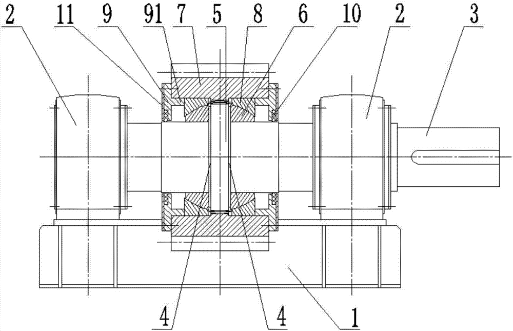
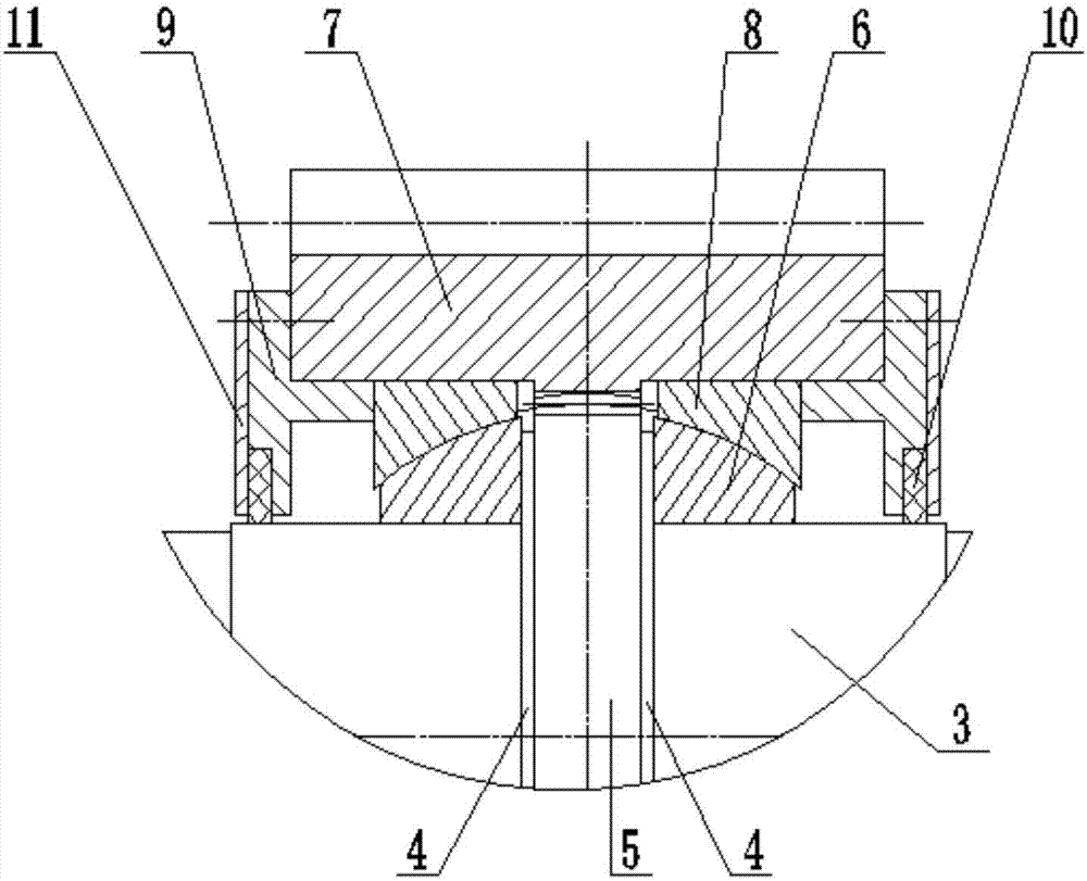
[0016] Such as figure 1 As shown, the embodiment of the present invention provides a floating gear transmission device, which includes a base 1, two bearing seats 2 are installed on the base 1, and a bearing is respectively installed in the two bearing seats 2 (not shown in the figure). shown), a support shaft 3 is installed in the two bearings, and the middle part of the support shaft 3 is provided with two shaft shoulders 4, and the support shaft 3 is also provided with a first gear 5, and the first gear 5 is arranged between the two shaft shoulders 4 between. Two inner ball bushes 6...


PUM


Abstract

The invention discloses a floating-type gear transmission device which comprises a base. The base is provided with two bearing pedestals, and bearings are installed in the corresponding bearing pedestals. A supporting shaft is installed in the bearings, and two shaft shoulders are arranged in the middle of the supporting shaft. A first gear is arranged on the supporting shaft and located between the two shaft shoulders, and inner spherical tiles are arranged on the supporting shaft and located at the two outer sides of the shaft shoulders correspondingly. A second gear is arranged at the outer side of the first gear. The inner side of the second gear is engaged with the first gear. The outer sides of the inner spherical tiles are provided with outer spherical tiles matched with the inner spherical tiles separately. The two sides of the second gear are each fixedly connected with a transparent cover, and a distance is kept between the inner side of the middle part of each transparent cover and the supporting shaft. Each transparent cover comprises a limiting part, and the limiting parts are connected with the corresponding outer spherical tiles. According to the floating-type gear transmission device, the spherical tile structure is adopted, the purpose that the gears can swing along with swinging of driven gears can be achieved, and the tooth surface combining condition is effectively improved; and the spherical tiles are simple in structure, the gear size cannot be greatly increased, cost is low, the second gear and the supporting shaft are in gear connection, and the supporting shaft cannot swing.

Description

technical field [0001] The invention relates to the field of transmission devices, in particular to a floating gear transmission device. Background technique [0002] Gear transmission is widely used in various mechanical equipment, especially in asymmetric gear pairs such as tube mills and rotary kilns. Due to the bending of the equipment, the contact coefficient of the tooth surface of the gear is low, and the wear is not uniform, which also limits the transmission. ability. [0003] In the existing equipment, there are generally two ways to deal with it. The first one: most of them are installed in parallel, and generally do not deal with the non-parallel joint surface caused by the bending of the equipment during operation. In order to improve the service life, Generally, the strength of the gear is improved, the degree of surplus is increased, and the opposite side is used after a certain period of wear. The second method is to add a rubber pad to the gear base to i...

Claims


Application Information

Patent Timeline
IPC IPC(8): F16H1/10F16H57/022F16H57/023
CPCF16H1/10F16H57/022F16H57/023F16H2057/02069
Inventor 周建铭谭长明许广丰赵玉会贾小朋
Owner NANJING XIPU CEMENT ENG GROUP
Why Eureka
Try Eureka