
An anti-cavitation spool structure

A cavitation and spool technology, applied to valve details, valve devices, sliding valves, etc., can solve the problems of hydraulic system efficiency reduction, failure, etc., to reduce cavitation damage, simple structure, and reduce spool cavitation The effect of destruction

Active Publication Date: 2019-07-09
ZHEJIANG UNIV
View PDF3 Cites 1 Cited by
  • Summary
  • Abstract
  • Description
  • Claims
  • Application Information

AI Technical Summary

Problems solved by technology

Cavitation damage of key components will reduce the efficiency of the hydraulic system or even fail

Method used


Image

  • An anti-cavitation spool structure
  • An anti-cavitation spool structure
  • An anti-cavitation spool structure

Examples


Embodiment Construction

[0026] The present invention will be described in further detail below in conjunction with the accompanying drawings and specific embodiments.

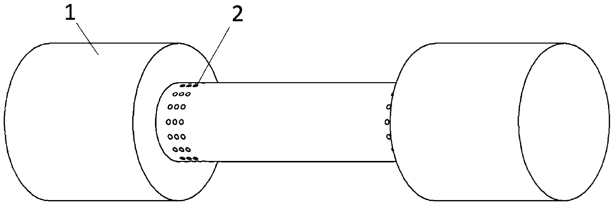
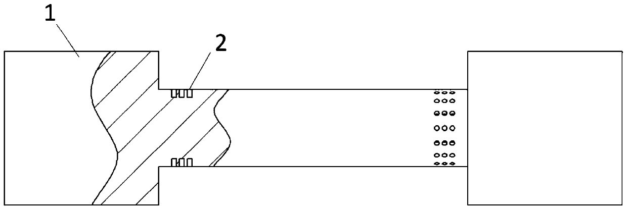
[0027] Such as figure 1 and figure 2 As shown, the embodiment of the present invention is aimed at the spool of the cylindrical valve in the slide valve. Blind holes are arranged along multiple circumferences on the peripheral surface of the cylindrical valve facing the liquid inlet as cavitation induction holes 2. The cavitation of each circumference The induction holes 2 are evenly spaced along the circumferential direction.

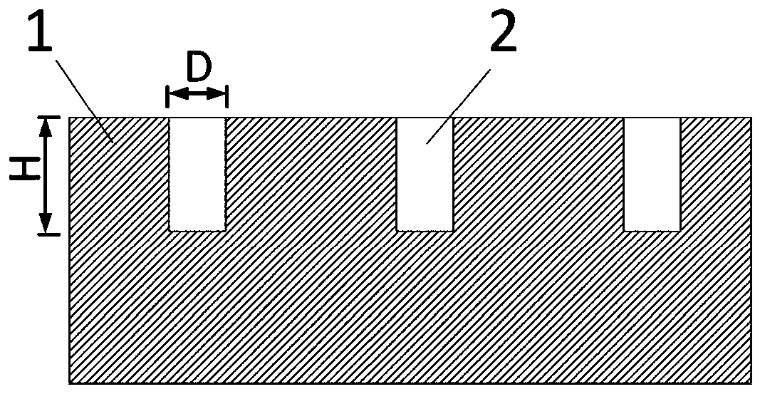
[0028] In a specific implementation, the diameter D of the cavitation induction hole 2 is 0.5mm-5mm, the depth H is 1mm-10mm, and H=2D. Preferably, the depth H of the induced hole is 2D.

[0029] Such as Figure 4 As shown, water flows through the slide valve during implementation. After testing, it is found that:

[0030] When the cavitation-inducing hole does not exist, the collapse jet of the cavitati...


PUM

PropertyMeasurementUnit
diameteraaaaaaaaaa
depthaaaaaaaaaa

Abstract

The invention discloses a cavitation resistant valve core structure. Cavitation induction holes used for cavitation resistance are formed in a part, likely to be cavitated, of a valve core. The part likely to be cavitated is the part or the surface, impacted by liquid, on the valve core. The cavitation induction holes are uniformly formed in the surface of the valve core along the circumference. The cavitation induction holes can effectively guide cavitation jets into the cavitation induction holes, and cavitation collapse jet kinetic energy is consumed through fluids in the cavitation induction holes, so that impact of cavitated bubble collapse jets on the important part of a valve body is avoided, and cavitation on the surface of the valve body is reduced or suppressed.

Description

technical field [0001] The invention relates to hydraulic, chemical and other industrial fields, in particular to a spool structure for inducing cavitation and reducing damage to the important surface of the spool by cavitation, as a protection device for the important spool in the hydraulic system. Background technique [0002] Fluid machinery such as hydraulic pumps, valves and water conservancy machinery are subject to cavitation in modern high-demand applications. Cavitation refers to the process that when the partial pressure of the fluid is lower than the vaporization pressure of the liquid, steam or gas is formed inside the liquid to form vapor bubbles, that is, cavitation bubbles. When the cavitation bubble flows from the low-pressure area to the high-pressure area, the volume shrinks and collapses under the action of the high pressure of the surrounding liquid, followed by pressure shock waves, high-speed micro jets, and luminescence. Serious consequences such as c...

Claims


Application Information

Patent Timeline
Patent Type & Authority Patents(China)
IPC IPC(8): F16K47/02F16K47/04F16K3/314
CPCF16K3/314F16K47/02F16K47/04
Inventor 邹俊李博吉晨杨华勇
Owner ZHEJIANG UNIV
Learn More