Scanning type pipeline leakage detecting mechanism

A leak detection and scanning technology, which is applied in pipeline systems, mechanical equipment, gas/liquid distribution and storage, etc., can solve problems such as safety hazards, perforation, and accelerated pipeline wall perforation, so as to improve the accuracy and stability of pressure measurement, Effects of improving safety performance and improving detection accuracy

Inactive Publication Date: 2017-11-07
马鞍山英维爱生态科技有限公司
View PDF0 Cites 8 Cited by
  • Summary
  • Abstract
  • Description
  • Claims
  • Application Information

AI Technical Summary

Problems solved by technology

[0002] The pipeline is a device connected by pipes, pipe connectors and valves to transport gas, liquid or fluid with solid particles. In the field of hazardous gas production and transmission applications, the pipeline needs to be completely sealed. If a leak occurs, it may cause In major safety accidents, in the high-pressure main pipeline, due to the high gas pressure and fast flow rate, the gas flow rate in the pipeline exceeds a certain range, which will generate scour force, damage the pipeline wall, and eventually cause perforation, resulting in leakage. At the same time, gas corrosion It also further accelerates the perforation of the pipeline wall. Since the manual use of instruments to detect gas leakage has a certain lag, it is difficult to detect the leakage immediately after the leakage occurs, resulting in a large amount of dangerous gas being discharged outside the site, which poses a great safety hazard.

Method used


Image

  • Scanning type pipeline leakage detecting mechanism
  • Scanning type pipeline leakage detecting mechanism
  • Scanning type pipeline leakage detecting mechanism

Examples


Embodiment Construction

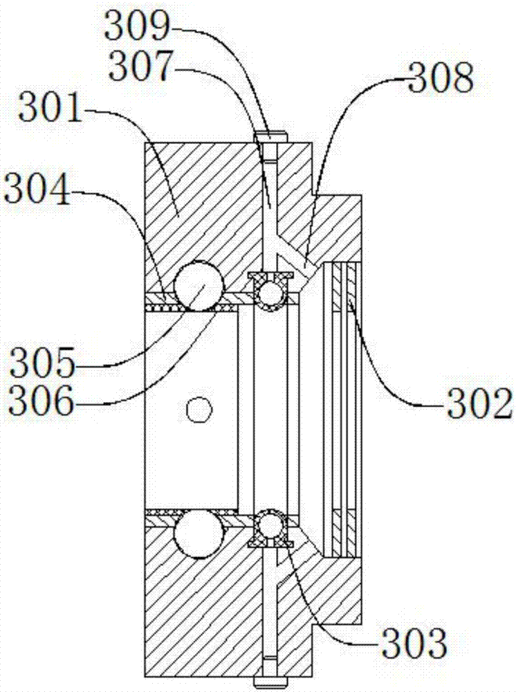
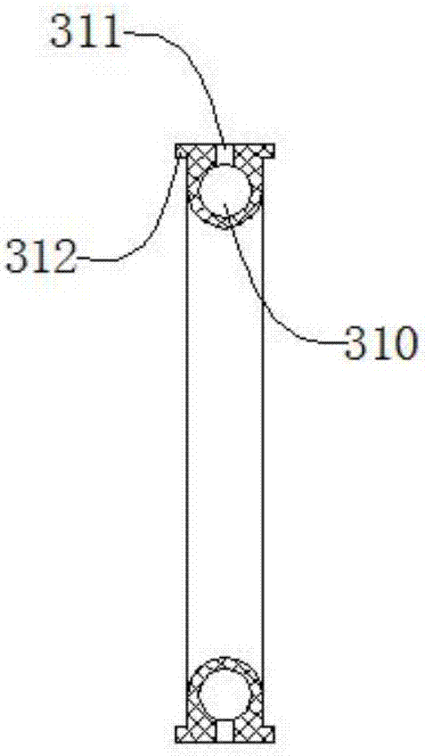
[0033] Such as figure 1 , figure 2 , image 3 , Figure 4As shown, a scanning pipeline leakage detection mechanism includes a base 1, a pipeline 2, a sealing mechanism 3 symmetrically arranged in two pieces along the pipeline 2, a connecting pipe 4, a pressure gauge 5, a servo motor 6, and a screw 7 , feed nut 8, sliding seat 9, support frame 10, the sealing mechanism 3 is located on the outside of the pipeline 2, the sealing mechanism 3 is connected to the pipeline 2 with a gap, and the connecting pipe 4 is located in the two symmetrically arranged sealing Between the mechanisms 3, the connecting pipe 4 is connected to the sealing mechanism 3 by welding, the pressure gauge 5 is located outside the connecting pipe 4, the pressure gauge 5 is threadedly connected to the connecting pipe 4, and the servo motor 6 is located on the The upper end of the base 1, the servo motor 6 is threadedly connected with the base 1, the lead screw 7 is located on one side of the servo motor 6 ...


PUM


Abstract

The invention discloses a scanning pipeline leakage detection mechanism, which comprises a base, a pipeline, two sealing mechanisms symmetrically arranged along the pipeline, a connecting pipe, a pressure gauge, a servo motor, a lead screw, a feed nut, and a sliding seat , a support frame, the sealing mechanism also includes a sealing seat, a number of not less than 3 sealing rings uniformly distributed along the sealing seat, a sealing rubber ring, a retaining ring, a steel ball, a rubber sleeve, a first inlet The air passage, the second air inlet passage, the plug, the servo motor drives the connecting pipe to move, and scans the pipe for inspection. When the pressure detected by the pressure gauge exceeds the set value, the servo motor stops and the leaking part is sealed. The device has a simple structure. Through scanning detection, it can perform real-time detection on the entire pipeline to improve safety performance. It adopts a floating design and uses three-stage sealing to effectively prevent the leakage of gas from being discharged, so that the leaked gas is filled with the connecting pipe, which effectively improves detection. precision.

Description

technical field [0001] The invention relates to a mechanical device, in particular to a scanning pipeline leakage detection mechanism. Background technique [0002] The pipeline is a device connected by pipes, pipe connectors and valves to transport gas, liquid or fluid with solid particles. In the field of hazardous gas production and transmission applications, the pipeline needs to be completely sealed. If a leak occurs, it may cause In major safety accidents, in the high-pressure main pipeline, due to the high gas pressure and fast flow rate, the gas flow rate in the pipeline exceeds a certain range, which will generate scour force, damage the pipeline wall, and eventually cause perforation, resulting in leakage. At the same time, gas corrosion It also further accelerates the perforation of the pipeline wall. Since there is a certain lag in the manual use of instruments to detect gas leakage, it is difficult to detect the leakage immediately after the leakage occurs, resu...

Claims


Application Information

Patent Timeline
Patent Type & Authority Applications(China)
IPC IPC(8): F17D5/02
CPCF17D5/02
Inventor 王良超吴星星王恒斌
Owner 马鞍山英维爱生态科技有限公司
Why Eureka
Try Eureka