Supercharge Your Innovation With Domain-Expert AI Agents!

Method and device for realizing spontaneous sequential flowage of multiple parts of liquid

A liquid and sequential technology, applied in the field of microfluidics, can solve problems such as occupying working time and affecting work efficiency, and achieve the effect of improving work efficiency and saving labor time

Active Publication Date: 2017-11-07
CHANGCHUN INST OF OPTICS FINE MECHANICS & PHYSICS CHINESE ACAD OF SCI
View PDF5 Cites 0 Cited by
  • Summary
  • Abstract
  • Description
  • Claims
  • Application Information

AI Technical Summary

Problems solved by technology

At present, the above-mentioned purification operation needs to manually add different processing reagents to the sample one at a time. The repeated reagent addition operation takes up a lot of working time and seriously affects the work efficiency.

Method used


Image

  • Method and device for realizing spontaneous sequential flowage of multiple parts of liquid
  • Method and device for realizing spontaneous sequential flowage of multiple parts of liquid
  • Method and device for realizing spontaneous sequential flowage of multiple parts of liquid

Examples


Embodiment 1

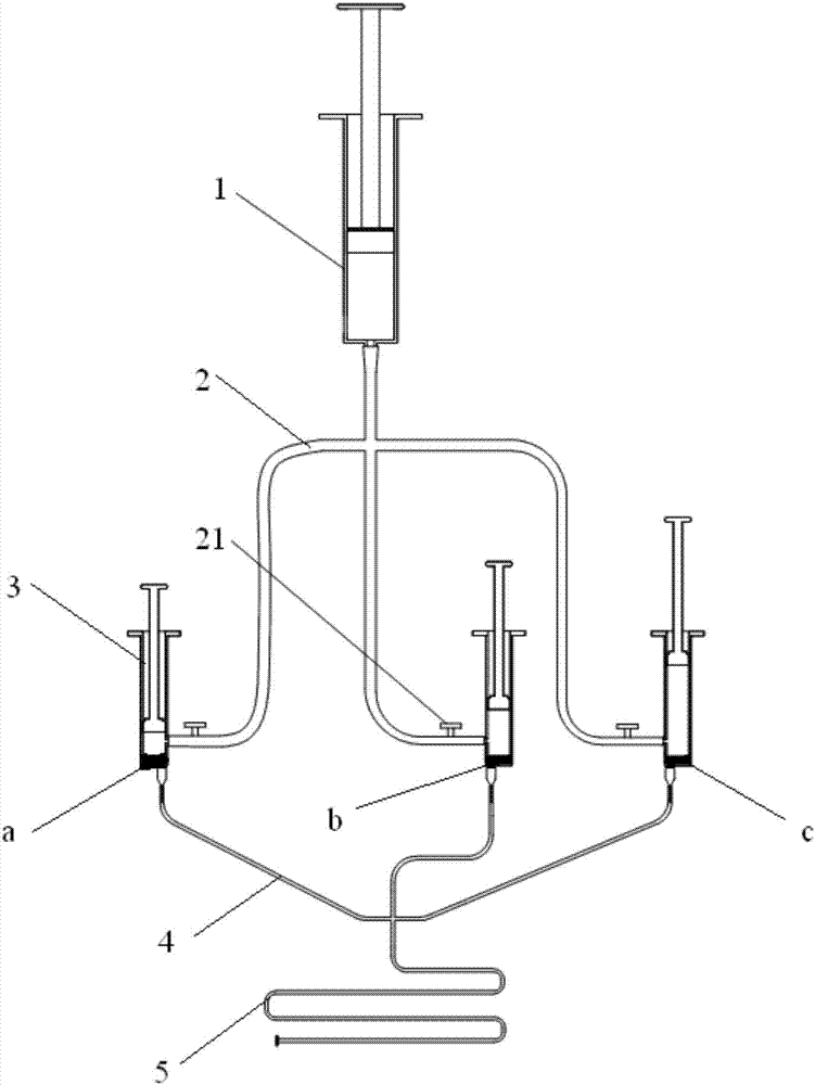
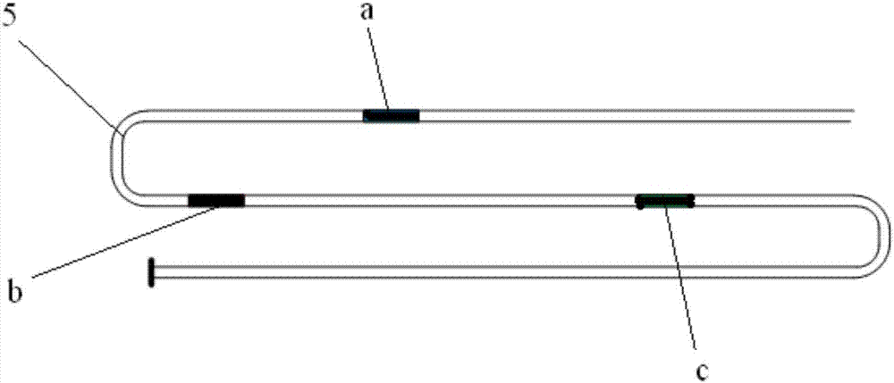
[0034] In Embodiment 1, the pressurizer 1 and the airtight container 3 are syringes, specifically, a 20ml syringe is used as the pressurizer 1, three 5ml syringes are used as the airtight container 3, and the three airtight containers 3 are connected to the air supply pipe 2 and the airtight container 3. The compressor 1 is connected, and the gas filling pipe 2 has an air inlet valve 21 near the airtight container 3 . Fix the three airtight containers 3 to the positions of 1ml, 3ml and 5ml respectively, and inject 100 microliters of blue ink a, red ink b and green ink c into the three airtight containers 3 respectively. The end of airtight container 3 links to each other with the connecting pipe 4 that flow path volume is all equal, and three connecting pipes 4 are connected with micropipe 5 by four-way pipe, and the end of micropipe 5 is connected with exhaust valve (not marked among the figure).

[0035] After completing the assembly of the device, close the exhaust valve at...

Embodiment 2

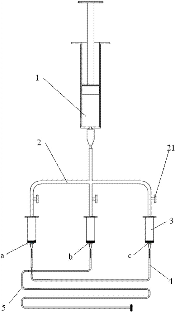
[0037] In the second embodiment, the pressurizer 1 and the airtight container 3 are syringes, specifically, a 20ml syringe is used as the pressurizer 1, and three 5ml syringes are used as the airtight container 3, and the three airtight containers 3 are connected to the air supply pipe 2 and the airtight container 3. The compressor 1 is connected, and the gas filling pipe 2 has an air inlet valve 21 near the airtight container 3 . Fix the three airtight containers 3 to the positions of 2ml, and inject 100 microliters of blue ink a, red ink b and green ink c into the three airtight containers 3 respectively. The end of the airtight container 3 is connected to the connecting pipe 4 with different flow channel volumes, wherein the blue ink a corresponds to the connecting pipe 4 with a length of 10 cm, the red ink b corresponds to the connecting pipe 4 with a length of 20 cm, and the green ink c corresponds to the connecting pipe 4. The length of pipe 4 is 40cm, and three connecti...


PUM


Abstract

The invention provides a method and a device for realizing the spontaneous sequential flowage of multiple parts of liquid. The method is characterized by comprising the following steps of firstly, carrying out gas charging pressurization in a system consisting of closed containers (3) and connecting pipes (4), so as to enable the internal pressure intensity of the system to be more than external pressure intensity, afterwards, intercepting a part of gas with high pressure intensity respectively through the blockage of the liquid, finally, communicating converged and communicated ends of the connecting pipes (4) with the exterior of the system, so as to form a pressure difference among the closed container (3) and the connecting pipes (4); hence, the liquid spontaneously flows under the action of a high-pressure gas; however, when the volumes of the closed containers (3) are each different and the flow passage volumes of the connecting pipes (4) are all equal, or when the volumes of the closed containers (3) are all the same and the flow passage volumes of the connecting pipes (4) are each unequal, therefore, the time when each part of liquid reaches the corresponding converged and communicated end of the connecting pipes (4) is different; thus, the sequential flowage of the multiple parts of liquid is realized.

Description

technical field [0001] The invention relates to the field of microfluidic technology, in particular to a method and device for realizing the spontaneous sequential flow of multiple liquids. Background technique [0002] In the field of biology and chemistry, the operation of purifying a certain substance is often encountered. During the purification, various liquids (processing reagents) are often required to process the samples to be purified in sequence. At present, the above-mentioned purification operation requires manual addition of different treatment reagents to the sample one at a time, and repeated reagent addition operations take up a lot of working time and seriously affect work efficiency. [0003] Therefore, how to realize the sequential addition of various reagents to the sample through simpler operations, so as to save labor time and improve work efficiency, has become a technical problem to be solved urgently by those skilled in the art. Contents of the inv...

Claims


Application Information

Patent Timeline
IPC IPC(8): G01N35/10
CPCG01N35/10G01N2035/1044
Inventor 吴文明穆全全李渊明
Owner CHANGCHUN INST OF OPTICS FINE MECHANICS & PHYSICS CHINESE ACAD OF SCI
Features
  • R&D
  • Intellectual Property
  • Life Sciences
  • Materials
  • Tech Scout
  • Unparalleled Data Quality
  • Higher Quality Content
  • 60% Fewer Hallucinations
Learn More