
Low profile low RCS ultra wide band wide-angle scanning strong mutual coupling phased array antenna based on polarization conversion metamaterial
A phased array antenna and polarization conversion technology, which is applied to antenna combinations, antennas, antenna arrays and other directions with different interactions, can solve problems such as being in the blank stage, and achieve the effects of reducing self-weight, lifting capacity, and reducing impedance
- Summary
- Abstract
- Description
- Claims
- Application Information
AI Technical Summary
Problems solved by technology
Method used
Image

Examples
Embodiment 1
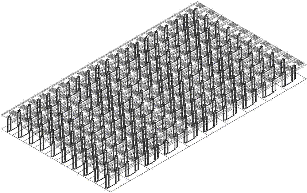
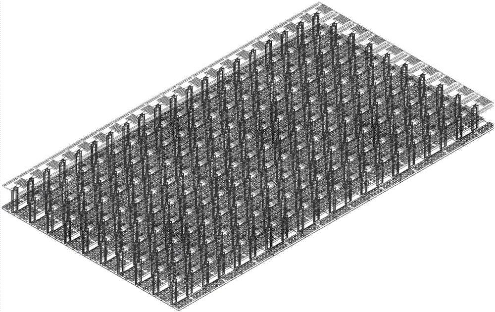
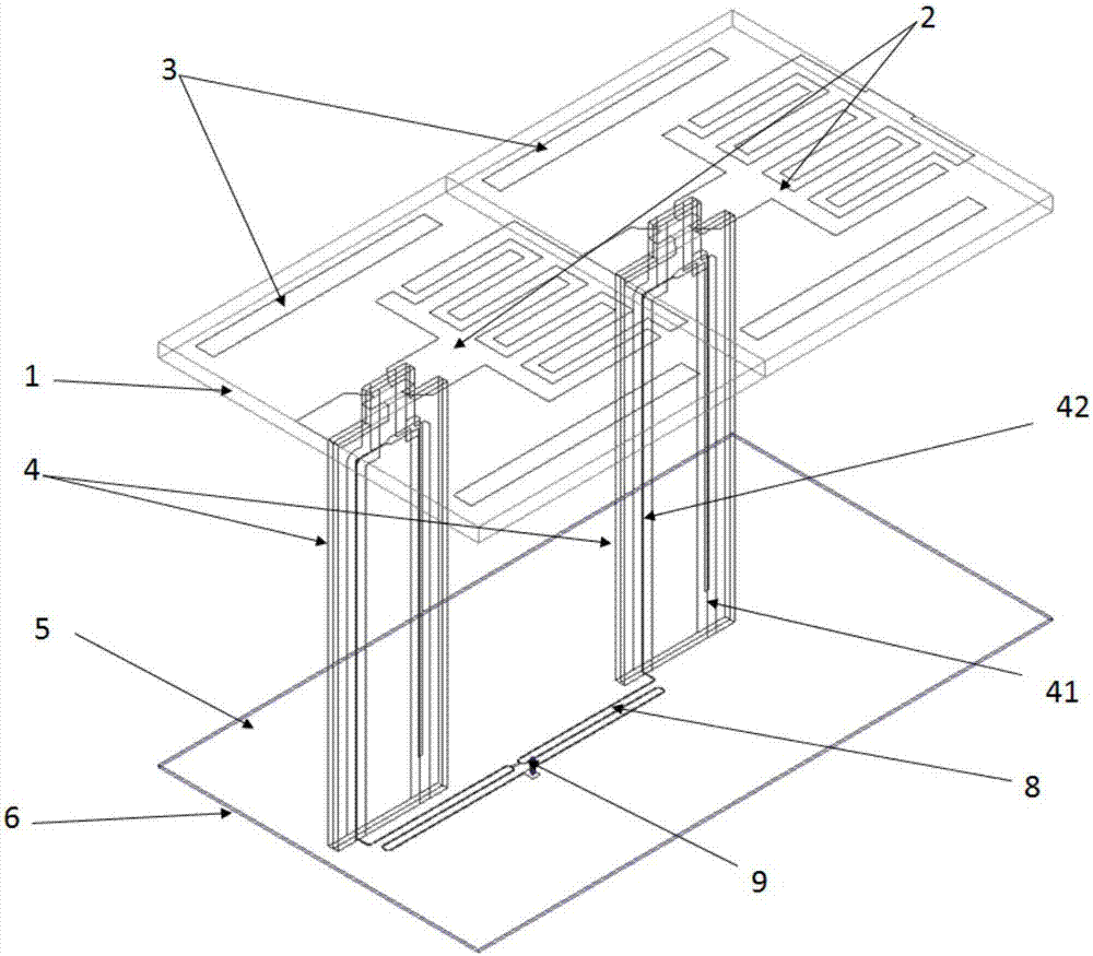
[0031] refer to figure 1 and figure 2 , the two array antennas in this embodiment are composed of a periodic structure of antenna sub-array units printed with closely arranged dipole units. Its structure includes a dielectric substrate (1); an interdigitated dipole unit (2) printed on the dielectric substrate; a rectangular patch (3) printed on both sides of the dipole; a strip-shaped patch located under the antenna dielectric substrate. wire balun (4); a medium layer (6) located below the balun and having a metal floor layer (5) on the upper surface; a one-to-two-centimeter network (8) printed on the lower surface of the medium layer; Microwave coaxial cable (9). The only difference in its structure is that figure 2 The shown antenna structure also includes a polarization conversion material (7) loaded on the metal floor above the dielectric layer. The height of the whole antenna is only 0.267 times of the high-frequency wavelength, which meets the low-profile requireme...
PUM
 Abstract
Description
Claims
Application Information