Burst optical signal receiving circuit and optical module

A technology for receiving circuits and light-emitting signals, which is applied in the field of optical communication, and can solve problems such as heavy output AC load, quality degradation of the output signal of the limiting amplifier 20, and impact on burst receiving sensitivity, so as to improve sensitivity and ensure signal transmission quality.

Inactive Publication Date: 2017-11-07
HISENSE BROADBAND MULTIMEDIA TECH
View PDF6 Cites 2 Cited by
  • Summary
  • Abstract
  • Description
  • Claims
  • Application Information

AI Technical Summary

Problems solved by technology

[0004] However, since the above two limiting amplifiers are connected in parallel, compared to the source-end transimpedance amplifier 20, its output impedance is actually equivalent to a differential 51ohm, resulting in the output impedance of the two limiting ampli

Method used


Image

  • Burst optical signal receiving circuit and optical module
  • Burst optical signal receiving circuit and optical module
  • Burst optical signal receiving circuit and optical module

Examples


Example Embodiment

[0017] Exemplary embodiments will be described in detail herein, examples of which are illustrated in the accompanying drawings. Where the following description refers to the drawings, the same numerals in different drawings refer to the same or similar elements unless otherwise indicated. The implementations described in the illustrative examples below are not intended to represent all implementations consistent with the present invention. Rather, they are merely examples of apparatus and methods consistent with some aspects of the invention as recited in the appended claims.

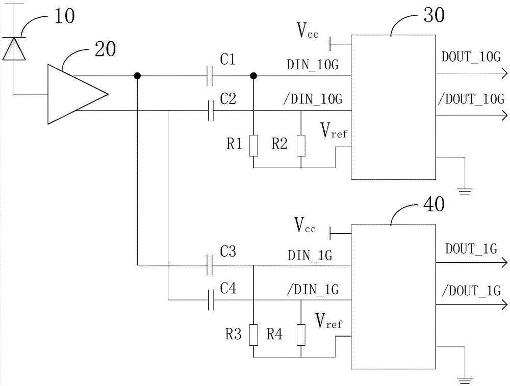
[0018] For the 10G EPON symmetrical OLT optical module in the prior art, the upstream receiving mode is burst state, compatible with 10G / 1G, and the two rates share one APD and TIA, and the TIA access rate is 1.25G and 10.3125G LA respectively. Since the two LAs are in parallel state, compared with the TIA source end, the TIA output impedance does not match the source end and the TIA output AC load is...


PUM

PropertyMeasurementUnit
Capacitanceaaaaaaaaaa

Abstract

The invention relates to a burst optical signal receiving circuit and an optical module. A signal amplifier circuit is designed between an output end of a trans-impedance amplifier and input ends of limiting amplifiers in a burst circuit. The input end of the signal amplifier circuit is connected with the output end of the trans-impedance amplifier. The output end of the signal amplifier circuit is connected with the input ends of a first limiting amplifier and a second limiting amplifier. The input impedance of the signal amplifier circuit matches the output impedance of the trans-impedance amplifier. Signal implication can be carried out on 1G and 10G signals output by the trans-impedance amplifier without attenuation. The amplified signals are transmitted to 1G and 10G limiting amplifiers. After signal amplitudes are increased, a matching demand for the rear end impedance is reduced, so the condition that the signals output from the signal amplifier circuit to the limiting amplifiers are degraded in quality can be reduced, the small signal transmission quality from the trans-impedance amplifier to the limiting amplifiers can be ensured, and the sensitivity of the burst receiving circuit is improved.

Description

technical field [0001] The invention relates to the technical field of optical communication, in particular to a burst optical signal receiving circuit and an optical module. Background technique [0002] 10G EPON (Ethernet Passive Optical Network, Ethernet Passive Optical Network) symmetrical OLT (optical line terminal, optical line terminal) optical module, as a smooth upgrade of 1G EPON and 10G EPON asymmetrical OLT optical module, has become the field of optical access network The most popular technology, it can not only increase the existing bandwidth, but also increase the uplink and downlink rates to 10.3125Gbit / s, which greatly meets the user's demand for bandwidth, and also takes into account 1G and 10G services, compatible with EPON networking, unified and smooth network management The upgrade is highly favored by operators, and it also greatly reduces the investment and development costs of operators. [0003] Specifically, the 10G EPON symmetrical OLT optical mo...

Claims


Application Information

Patent Timeline
IPC IPC(8): H04B10/60H04Q11/00
CPCH04B10/60H04Q11/0003
Inventor 刘澍石良
Owner HISENSE BROADBAND MULTIMEDIA TECH
Why Eureka
Try Eureka