DMS (Data Management System) and CT data acquisition method

A technology for acquiring methods and data, which is applied in the field of communications and can solve problems such as increasing the complexity of DMS system design

Active Publication Date: 2017-11-07
SHANGHAI UNITED IMAGING HEALTHCARE
View PDF3 Cites 1 Cited by
  • Summary
  • Abstract
  • Description
  • Claims
  • Application Information

AI Technical Summary

Problems solved by technology

[0005] The purpose of the present invention is to provide a DMS system and a method for obtaining CT data, to solve the problem of using hardware triggers in the DMS system in the prior art to realize multiple DBB synchronization, due to the influence of hardware transmission, processing delay or jitter , the problem of increasing the design complexity of the EMC of the DMS system

Method used


Image

  • DMS (Data Management System) and CT data acquisition method
  • DMS (Data Management System) and CT data acquisition method
  • DMS (Data Management System) and CT data acquisition method

Examples


Embodiment 1

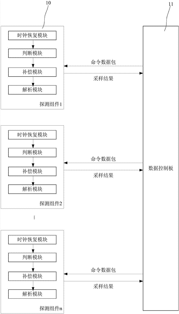
[0031] Please refer to figure 2 , which is a structural block diagram of the DMS system of the present invention, such as figure 2 As shown, the DMS system includes: a plurality of detection components 10 and a data control board 11 connected to the multiple detection components 10, each detection component 10 includes: a sequentially connected clock recovery module, a judgment module, a compensation module and Parsing module; each detection component 10 receives the command packet sent by the data control board 11, the command packet carries a clock signal and an acquisition trigger command, after the clock recovery module restores the clock signal in the command packet, The judging module judges the connection mode between different detection components (specifically, by responding to the ID configuration command, feeding back the connection mode between different detection components), and the compensation module performs time delay compensation for the current detection ...

Embodiment 2

[0038] Correspondingly, this embodiment also provides a method for acquiring CT data. Refer below Figure 4 Describe in detail.

[0039] First, step S1 is executed, the command data packet sent by the data control board to multiple detection components, the command data packet carries a clock signal and an acquisition trigger command, each detection component includes: a sequentially connected clock recovery module, a judgment module, Compensation module and analysis module;

[0040] Next, step S2 is executed, each detection component receives the command data packet sent by the data control board, and the respective clock recovery module of each detection component recovers the clock signal in the command data packet it receives;

[0041] Next, step S3 is executed, the judging module of each detection component judges the connection mode between different detection components, and feeds back the judgment result to the compensation module;


PUM


Abstract

The invention provides a DMS (Data Management System). The DMS comprises a plurality of detection assemblies and a data control panel connected with the plurality of detection assemblies, wherein the detection assemblies comprise compensation modules, clock recovery modules, resolving modules and judging modules; the detection assemblies are used for receiving a command data packet transmitted by the data control panel; the command data packet bears a clock signal and an acquisition triggering command; the judging modules are used for judging connection ways among different detection assemblies after the clock recovery modules recover the clock signal in the command data packet; and the compensation modules are used for performing time delay compensation on a current detection assembly according to a connection way, and performing trigger sampling according to acquisition triggering commands resolved by the resolving modules till all the detection assemblies are subjected to time delay compensation. The clock signal and the acquisition triggering command are borne in the command data packet, so that the influence of hardware transmission or jittering on implementation of synchronization of the plurality of detection assemblies in a hardware triggering way is avoided, and the design of EMC (Electro Magnetic Compatibility) of the DMS is simplified.

Description

technical field [0001] The invention relates to the field of communication technology, in particular to a DMS system and a method for acquiring CT data. Background technique [0002] In a complex sensing acquisition system, such as CT's DMS (Data Management System) system, it often includes as many as tens of thousands to hundreds of thousands of sensing units, which are integrated by chips, considering channel bandwidth and heat dissipation. , These sensing units are composed of up to dozens of detection modules (DBB). [0003] According to the integration principle of the detector, to ensure that each sensing unit of the detector has a consistent response to time, it is necessary to ensure that the deviation between the start time of the acquisition and the end time of the acquisition is within the predetermined range, so as not to affect the system indicators if the deviation is too large. Usually the size of the deviation needs to be controlled in the order of ns (10-9 ...

Claims


Application Information

Patent Timeline
Patent Type & Authority Applications(China)
IPC IPC(8): H04J3/06H04L7/00H04W56/00
CPCH04J3/06H04J3/0602H04J3/0617H04L7/0012H04L7/0037H04W56/004H04W56/0045
Inventor 杨隆梓
Owner SHANGHAI UNITED IMAGING HEALTHCARE
Why Eureka
Try Eureka