Shoe upper head position control structure in upper grabbing process, and upper grabbing method

A technology of head position and control structure, which is applied in the direction of shoe last, footwear, application, etc., can solve the problems of inconspicuous improvement in production efficiency, and achieve the effect of tight fit, improved operation, and guaranteed product quality

Active Publication Date: 2017-11-10
TAIZHOU CHUANGXIAN ELECTRONICS TECH CO LTD
View PDF10 Cites 1 Cited by
  • Summary
  • Abstract
  • Description
  • Claims
  • Application Information

AI Technical Summary

Problems solved by technology

[0006] There are still some deficiencies in the existing shoe upper grasping upper line tensioning device: the improvement of production efficiency is not obvious

Method used


Image

  • Shoe upper head position control structure in upper grabbing process, and upper grabbing method
  • Shoe upper head position control structure in upper grabbing process, and upper grabbing method
  • Shoe upper head position control structure in upper grabbing process, and upper grabbing method

Examples


Embodiment 1

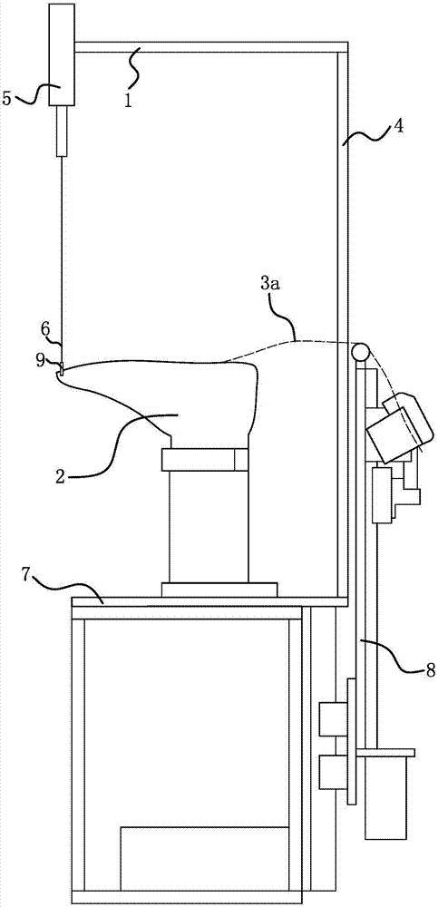
[0025] Such as figure 1 As shown, the head position control structure of the shoe upper 3 in the upper gripping process includes a bracket 1 and a positioning member 9 .

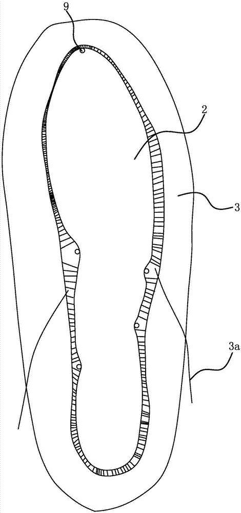
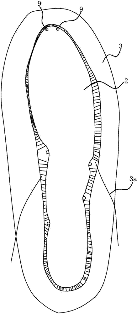
[0026] The positioning member 9 is a positioning rod, and the number of the positioning rods is 1-3. Instructions attached figure 2 The number of positioning rods given is one, and the instructions are attached image 3 The number of positioning rods is given as two.

[0027] Positioning holes are arranged on the shoe last 2, and the number of positioning holes is the same as that of the positioning rods. The surface corresponding to the bottom opening of the shoe upper 3 in the shoe last 2 is the bottom surface; when the upper is grasped, the bottom surface of the shoe last 2 faces upward. The positioning holes are located on the bottom surface of the shoe last 2 head.

[0028] When the positioning piece 9 is inserted in the positioning hole and the shoe last 2 is covered with the upper 3, the positio...

Embodiment 2

[0033] The structure and principle of this embodiment are basically the same as that of Embodiment 1, and the basic similarities will not be redundantly described, and only the differences will be described, and the differences are as follows: Figure 4 As shown, the positioning member 9 is an arc-shaped metal sheet, and the number of the metal sheet is one. The positioning hole is strip-shaped and arc-shaped, and the shape of the positioning hole matches the shape of the metal sheet.


PUM


Abstract

The invention provides a shoe upper head position control structure in an upper grabbing process, and an upper grabbing method, and belongs to the technical field of shoes. The problem of insufficient production efficiency in the existing process for tensioning an upper grabbing line by an upper-grabbing line pulling device is solved. The shoe upper head position control structure in the upper grabbing process comprises a bracket and a positioning piece; a positioning hole is formed in a shoe tree; when the positioning piece is inserted into the positioning hole, the positioning piece can limit the movement stroke of the shoe upper head from the head of the shoe tree to the heel part; the positioning piece is connected with a pull rope; and a driving piece capable of pulling the pull rope to enable the positioning piece to do lifting motion is arranged on the bracket. In the process of performing upper grabbing operation by the upper-grabbing line pulling device and the shoe upper head position control structure, the shoe upper adjusting amplitude and the time required by adjustment are obviously reduced, so that the force application pausing time of the upper-grabbing line pulling device is obviously reduced, even the upper-grabbing line pulling device can continuously output the action force, the reality required by completion of the upper grabbing process is obviously reduced, and the production efficiency of the upper grabbing process is obviously improved.

Description

technical field [0001] The invention belongs to the technical field of shoes, and relates to a shoe-making device, in particular to a position control structure of a shoe upper head used in the upper grabbing process. [0002] The invention belongs to the technical field of footwear, and relates to a shoe-making device, in particular to a method for grasping an upper using a position control structure of a shoe upper head. Background technique [0003] Shoes are indispensable items in people's daily life. Shoemaking has the characteristics of complex processes and high technical requirements. At present, most processes in shoemaking are still manual operations. Taking running shoes as an example, first the upper and the sole are made separately, then the upper is put on the shoe last, the upper is grasped, and finally the glue is sprayed and the sole is covered. In the process of grabbing the upper of the shoe, it is necessary to tighten and stretch the upper of the shoe, ...

Claims


Application Information

Patent Timeline
Patent Type & Authority Applications(China)
IPC IPC(8): A43D9/00
CPCA43D9/00
Inventor 陈兵徐雅红
Owner TAIZHOU CHUANGXIAN ELECTRONICS TECH CO LTD
Why Eureka
Try Eureka