Rotary discharging type cosmetic container

A cosmetic container and spin-out technology, which is applied in cosmetic powder containers, cosmetic packaging, dressing containers, etc., can solve problems such as user property loss, cosmetic leakage, handbag pollution, etc., to meet the needs of use, easy to operate, The effect of avoiding leakage

Pending Publication Date: 2017-11-10
SHYA HSIN PACKAGING IND CHINA
View PDF0 Cites 2 Cited by
  • Summary
  • Abstract
  • Description
  • Claims
  • Application Information

AI Technical Summary

Problems solved by technology

However, when cosmetics are carried, they are usually placed in the handbag together with other items, and the handbag is often in a shaking state, which will easily cause the cosmetic container to appear loose, not only causing cosmetic leakage, Also caused pollution to the handbag, and then caused certain property loss to the user

Method used


Image

  • Rotary discharging type cosmetic container
  • Rotary discharging type cosmetic container
  • Rotary discharging type cosmetic container

Examples


Embodiment 1

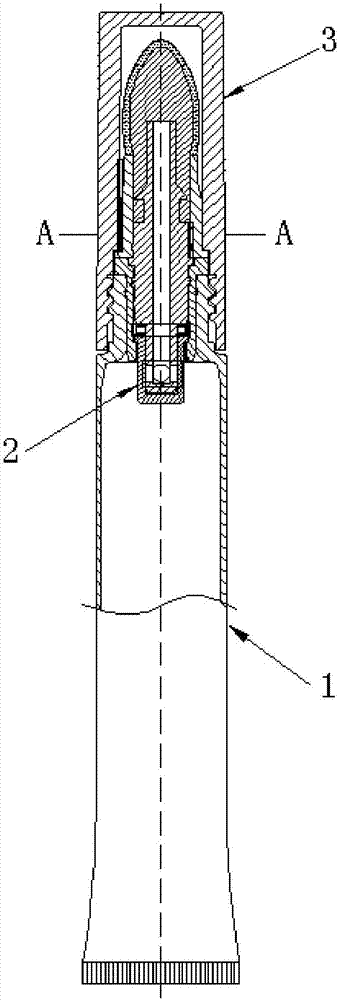
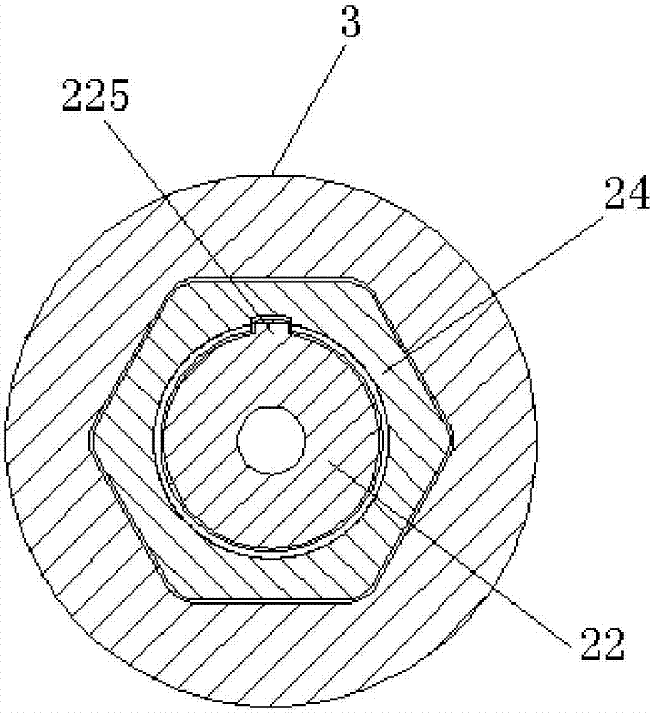
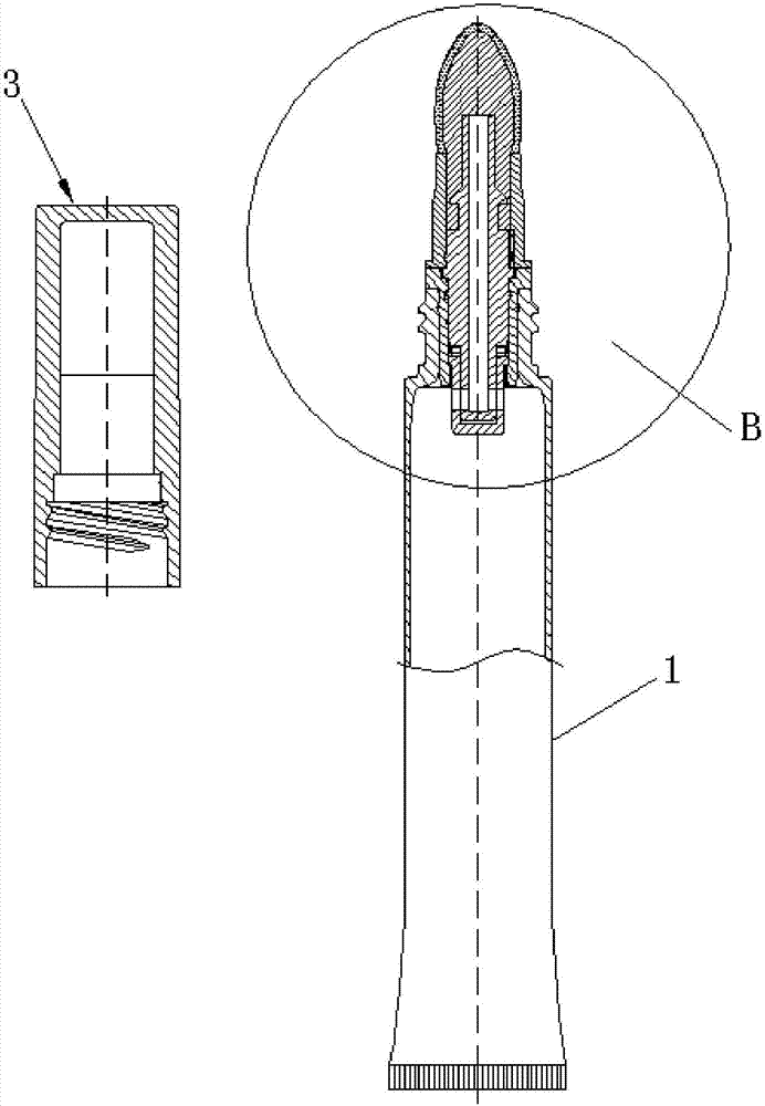
[0064] See attached figure 1 As shown, it is a schematic cross-sectional structure diagram of the first embodiment of the rotary discharge type cosmetic container of the present invention. The rotary discharge type cosmetic container includes a container body 1 for containing cosmetic liquid, a coating assembly 2 for drawing out the cosmetic liquid and applying it on the user's face, and a housing cover 3. One side of the coating component 2 is sealed and inserted into the opening 10 of the container body 1, the casing cover 3 is sleeved outside the coating component 2, and the casing cover 3 is also connected to the opening 10 In particular, the coating assembly 2 includes a plug 20, a spool sleeve 21 and a spool 22, see the attached Figure 4 As shown, the plug 20 is a sleeve-shaped structure with openings on both axial sides, and the plug 20 is tightly inserted into the opening 10; the valve core sleeve 21 is open on one side of the shaft and the other A hollow cylindrica...

Embodiment 2

[0080] See attached Figure 13 As shown, it is a schematic cross-sectional structure diagram of the second embodiment of the rotary discharge type cosmetic container of the present invention.

[0081] The structure of the rotary discharge type cosmetic container shown in embodiment 2 is basically the same as the rotary discharge type cosmetic container shown in embodiment 1, the main difference lies in the structure of the damping member. The structure of the damping member configured in Embodiment 2 is: on the outer wall of the valve core sleeve 21 and close to the position of the third overlapping edge 211, a ring-shaped fifth locking groove 214 is recessed, and another There is a sealing ring 25, the sealing ring 25 is embedded in the fifth clamping groove 214, and touches the inner side wall of the first overlapping edge 201 at the same time; wherein, the sealing ring 25 is the damping member (For details, please refer to the attached Figure 14 - attached Figure 16 sh...


PUM


Abstract

The invention discloses a rotary discharge cosmetic container, comprising a container body, a coating component and a shell cover sleeved outside the coating component. The coating component includes a plug, a valve core sleeve and a valve core, and the plug is tightly inserted into the coating component. In the opening part of the container main body, the valve core sleeve is placed in the container main body, and one axis side of the valve core sleeve is movably clamped in the plug one axis side, and the valve core sleeve is also provided with a first liquid outlet through hole; There is a valve core body, one shaft end of the valve core body is open and the other shaft end is closed, a discharge head is connected to one shaft end of the valve core body, and the other shaft end of the valve core body is inserted through the plug after being movably inserted. In the valve core sleeve, the valve core body is also provided with a second liquid outlet through hole; when the shell cover rotates relative to the container body, the shell cover can drive the valve core to rotate, and the rotation of the valve core can also make the first, The two liquid outlet through holes are overlapped and connected or are staggered and disconnected; this can improve the sealing performance of the cosmetic during carrying and avoid leakage.

Description

technical field [0001] The invention relates to the technical field of cosmetic containers, and specifically provides a rotary discharge type cosmetic container. Background technique [0002] With the development of the economy and the improvement of people's living standards, people begin to pay more and more attention to their image and health, especially women, the probability and frequency of using cosmetics are also increasing, such as eyelash brushes, eyeliners, lip brushes, etc. It is a cosmetic commonly used by women. [0003] The existing cosmetic container mainly realizes the plugging of the cosmetic after the cap is threadedly connected with the discharge head on the cosmetic container. However, when cosmetics are carried, they are usually placed in the handbag together with other items, and the handbag is often in a shaking state, which will easily cause the cosmetic container to appear loose, not only causing cosmetic leakage, Also polluted handbag, and then c...

Claims


Application Information

Patent Timeline
Patent Type & Authority Applications(China)
IPC IPC(8): A45D34/00A45D34/04
CPCA45D34/00A45D34/043A45D2034/002A45D2200/051A45D2200/054A45D2200/055
Inventor 钟华詹玲郎
Owner SHYA HSIN PACKAGING IND CHINA
Why Eureka
Try Eureka