
Cutting machine for metal machining

A metal processing and cutting machine technology, applied in the direction of metal processing machinery parts, metal processing equipment, manufacturing tools, etc., can solve the problems of manual replacement, waste of manpower, time waste, etc., achieve fast and accurate replacement, save work efficiency, and use convenient effect

Inactive Publication Date: 2017-11-10
深圳市越宏五金塑胶技术有限公司
View PDF6 Cites 0 Cited by
  • Summary
  • Abstract
  • Description
  • Claims
  • Application Information

AI Technical Summary

Problems solved by technology

[0002] The importance of cutting machines for metal cutting is self-evident. It can be said that without cutting machines, many metal materials cannot be processed into the desired shape. However, many of the current cutting machines are heavy and not easy to move. It cannot work when the power is supplied, which not only causes a waste of manpower but also a waste of time. At the same time, the existing cutting machine cannot automatically replace the cutting wheel and needs to be replaced manually, which wastes manpower and reduces work efficiency.

Method used


Image

  • Cutting machine for metal machining
  • Cutting machine for metal machining
  • Cutting machine for metal machining

Examples


Embodiment Construction

[0024] The preferred embodiments of the present invention will be described below in conjunction with the accompanying drawings. It should be understood that the preferred embodiments described here are only used to illustrate and explain the present invention, and are not intended to limit the present invention.

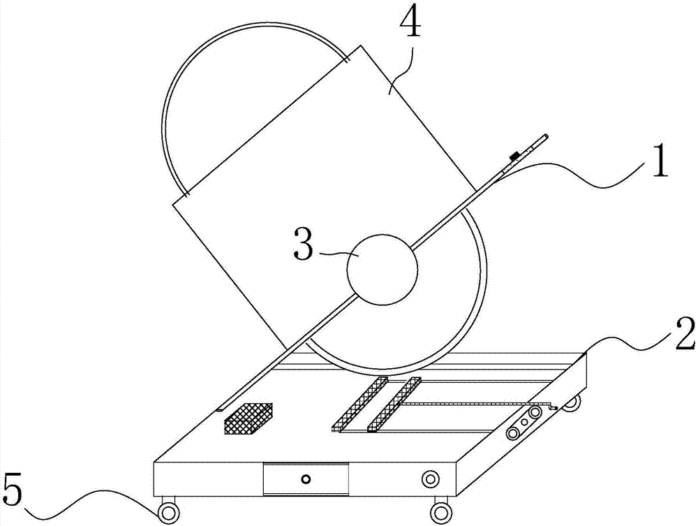
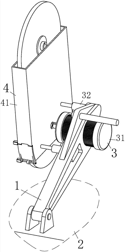
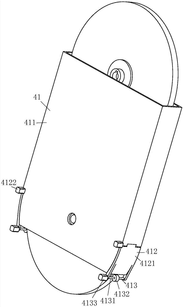
[0025] see Figure 1-5 , the present invention provides a technical solution: a cutting machine for metal processing, characterized in that it includes a bracket 1, a cutting machine base 2, a transmission main body 3, a wheel release device 4, a universal wheel 5, a cutting groove 10, a hand crank Rod 11, retractable rod button 12, retractable rod 13, universal wheel switch 14, slider groove 15, storage cabinet pull button 16, storage cabinet 17, motor 18, fixing part 19, sliding part 20, solar panel button 21, Solar panel 22 and power socket 23;

[0026] A support 1 is rotatably installed on the base 2 of the cutting machine, and the transmission main body 3 is i...


PUM

PropertyMeasurementUnit
thicknessaaaaaaaaaa

Abstract

The invention discloses a cutting machine for metal machining. The cutting machine comprises a bracket, a cutting machine base, a transmission body, a wheel device, universal wheels, a cutting groove, a hand rocking rod, a shrinkage rod button, a shrinkage rod, an universal wheel switch, a slide piece groove, a storage cabinet pull buckle, a storage cabinet, a motor, a fixed piece, a slide piece, a solar panel button, a solar panel and a power supply interface; the cutting groove is formed in the upper side of the cutting machine base; the shrinkage rod is arranged on the right side of the cutting machine base; the shrinkage rod button is arranged at the middle end of the shrinkage rod; the universal wheel switch is arranged at the right end of the front side of the cutting machine base; the storage cabinet is arranged on the left side of the universal wheel switch; the cutting machine is convenient to move through the universal wheels during moving; the power failure trouble can be solved through the solar panel; the cutting machine is simple in structure and convenient in use; and a cutting wheel can be automatically replaced without needing manual operation.

Description

technical field [0001] The invention relates to a cutting machine for metal processing, in particular to a cutting machine for metal processing. Background technique [0002] The importance of cutting machines for metal cutting is self-evident. It can be said that without cutting machines, many metal materials cannot be processed into the desired shape. However, many of the current cutting machines are heavy and not easy to move. It cannot work when the power is supplied, which not only causes a waste of manpower but also a waste of time. At the same time, the existing cutting machine cannot automatically change the cutting wheel, and needs to be replaced manually, which wastes manpower and reduces work efficiency. [0003] Therefore, how to design a cutting machine for metal processing that solves the above problems has become a problem that we will solve at present. Contents of the invention [0004] The object of the present invention is to provide a cutting machine fo...

Claims


Application Information

Patent Timeline
Patent Type & Authority Applications(China)
IPC IPC(8): B23Q1/01B23D79/00B23Q1/72
CPCB23D79/00B23Q1/01B23Q1/015B23Q1/72
Inventor 张帝高扬梁梦珂
Owner 深圳市越宏五金塑胶技术有限公司
Learn More