
Hypersonic-speed wave-riding duck wing aerodynamic layout

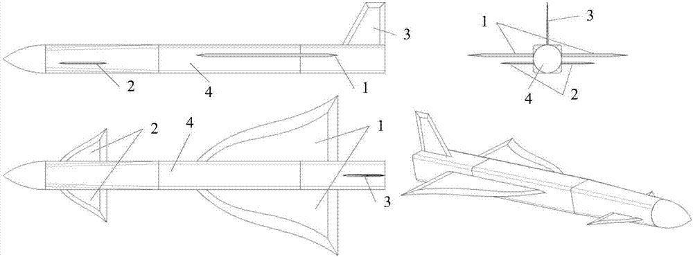
A hypersonic and aerodynamic layout technology, applied to supersonic aircraft, wings, motor vehicles, etc., to achieve the effect of increasing hypersonic aerodynamic performance, reducing the movement of aerodynamic focus, and avoiding large-scale movement

Active Publication Date: 2017-11-10
BEIHANG UNIV
View PDF6 Cites 6 Cited by
  • Summary
  • Abstract
  • Description
  • Claims
  • Application Information

AI Technical Summary

Problems solved by technology

In supersonic flow, the canard without waveriding design will still have high pressure leakage at the wingtip, but the affected area of ​​the vortex is limited to the Mach cone at the leading edge of the wingtip, which is much smaller than the subsonic situation

Method used


Image

  • Hypersonic-speed wave-riding duck wing aerodynamic layout
  • Hypersonic-speed wave-riding duck wing aerodynamic layout
  • Hypersonic-speed wave-riding duck wing aerodynamic layout

Examples


Embodiment 1

[0126] Embodiment 1: In the design state, the Mach number of incoming flow is 2, and the wedge angle is 4°. The leading edge of the waverider canard or main waverider wing is simplified into two connected wedges, one with sweep and one without sweep. The maximum waverider sweep angle determined by formulas (1) and (5) is 50.063°, as Figure 4 As shown in , the two cases with the sweep angles of 50° and 51° are compared: when the sweep angle is smaller than the maximum value of the waverider sweep angle, the leading edge of the model is an attached shock wave, as shown in the left sub-figure; when When the sweep angle is greater than the maximum value of the waverider sweep angle, the shock wave at the leading edge of the model is detached, and a small amount of high-pressure gas leaks, as shown in the sub-figure on the right. Numerical simulation results show that the critical relation of shock wave not detaching adopted in the present invention is applicable to the airfoil wa...

Embodiment 2

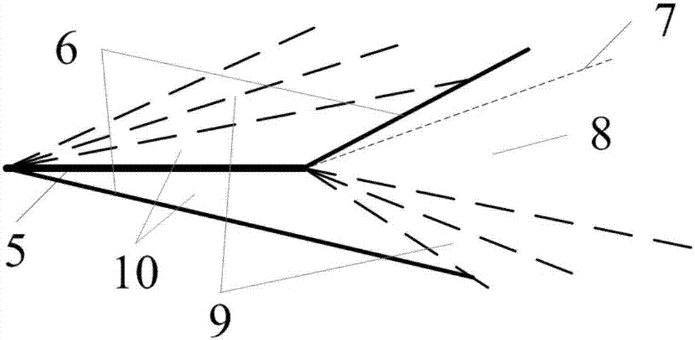
[0127] Embodiment 2: The flight Mach number in the design state is 6, the angle of attack is 10°, and the numerical simulation results of the characteristic line method of the simplified model of the waveriding canard two-dimensional flat plate are as follows Figure 5 and Figure 6 as shown, Figure 5 is the pressure coefficient cloud map, Figure 6 is the Mach number cloud map. It can be seen from the figure that oblique shock waves are generated on the lower surface of the leading edge of the plate 5, and an expansion fan-shaped area is formed on the upper surface; behind the shock wave and expansion wave at the leading edge, there is a uniform flow area near the upper and lower surfaces of the plate; at the trailing edge, behind the lower surface Expansion waves are generated at the trailing edge of the upper surface, and oblique shock waves are formed at the trailing edge of the upper surface; at the wake, the upper and lower surface pressures match, but the Mach number...


PUM


Abstract

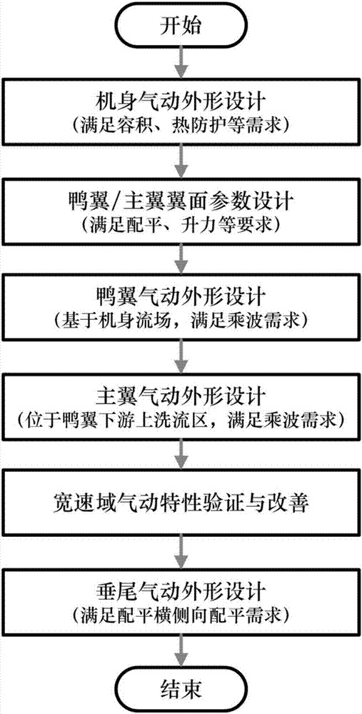
The invention discloses a hypersonic-speed wave-riding duck wing aerodynamic layout, and belongs to the design field of aerodynamic layout of a hypersonic-speed aircraft. The layout integrates a wave-riding design in selection of wing surface parameters of a duck wing and a main wing, so that hypersonic-speed aerodynamic characteristics of the aircraft can be improved while a capacity rate is guaranteed; the duck wing layout can greatly improve low-speed characteristics of the aircraft, and an aerodynamic focus of the aircraft can be prevented from greatly moving in a wide-speed area, so that low-speed and high-speed aerodynamic / controllability and stability are realized; opposite positions between a wave-riding duck wing and a wave-riding main wing are reasonably designed, and an effective angle of incidence of the main wing is increased by an up-washing region of wave-riding duck wing trail flow, so that the hypersonic-speed aerodynamic characteristics of the wave-riding main wing are further improved.

Description

technical field [0001] The invention belongs to the field of aerodynamic layout design of a hypersonic aircraft, in particular to an aerodynamic layout of a hypersonic waveriding canard. Background technique [0002] One of the main goals of hypersonic vehicle design is to pursue high lift-to-drag ratio in cruising state and take into account low and high-speed aerodynamic / controlling characteristics. [0003] From the perspective of improving high-speed aerodynamic performance, the waverider configuration is the first choice for a hypersonic vehicle to obtain a high lift-to-drag ratio in cruise state. The principle of the waverider configuration is to make the shock wave generated on the lower surface of the aircraft adhere to the leading edge through reasonable design, and use the attached shock wave to prevent the high-pressure flow on the lower surface from leaking to the upper surface, so that the high-pressure gas behind the wave on the lower surface can be used to obt...

Claims


Application Information

Patent Timeline
IPC IPC(8): B64F5/00B64C3/00B64C30/00
CPCB64C3/00B64C30/00B64F5/00
Inventor 蒋崇文胡姝瑶郭培旭高振勋李椿萱
Owner BEIHANG UNIV
Learn More