Intercept valve

A shut-off valve and valve body technology, applied in the field of shut-off valves, can solve problems such as shut-off valves out of control, and achieve the effect of ensuring safe and real-time detection

Pending Publication Date: 2017-11-10
NINGBO IDC INT TRADE
View PDF2 Cites 0 Cited by
  • Summary
  • Abstract
  • Description
  • Claims
  • Application Information

AI Technical Summary

Problems solved by technology

[0007] The purpose of the present invention is to solve the above-mentioned problems existing in the prior art, and to provide a shut-off valve, which can operate by itself in the eve

Method used


Image

  • Intercept valve
  • Intercept valve
  • Intercept valve

Examples


Example Embodiment

[0028] The specific embodiments of the present invention will be described in further detail below in conjunction with the drawings and embodiments. The following examples are used to illustrate the present invention, but cannot be used to limit the scope of the present invention.
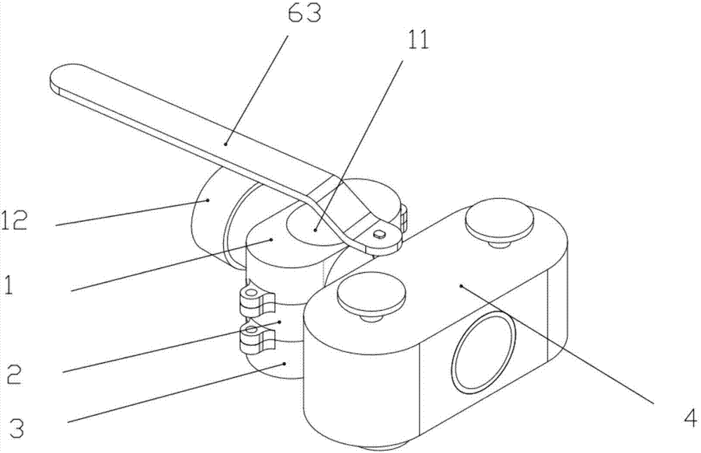
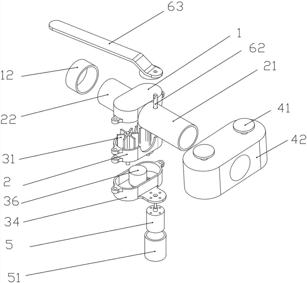
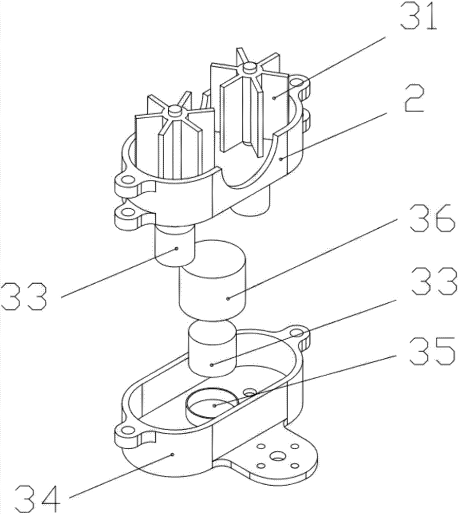
[0029] The structure of the shutoff valve of the embodiment of the present invention is as follows Figure 1 to 4 Shown includes: valve body 1, valve cover 2, power supply system 3, fire extinguishing system 4, motor 5 and valve; both ends of the valve body are provided with a first pipe body 21 and a second pipe body 22; the valve is located on the first pipe body Within 21; the fire extinguishing system 4 is set on the first pipe body 21; the valve cover 2 and the valve body 1 are connected with screws; the motor 5 is fixed with the power supply system 3, and the electrical connection between the motor 5 and the power supply system 3 is realized; 5 It can drive the valve to open and close.

[0030] ...


PUM


Abstract

The invention discloses a shut-off valve, which relates to the field of shut-off valves. The shut-off valve comprises: a valve body, a valve cover, a power supply system, a fire extinguishing system, a motor and a valve; a first pipe body and a second pipe body are arranged at both ends of the valve body The valve is set in the first pipe body; the fire extinguishing system is sleeved on the first pipe body; the valve cover and the valve body are connected by screws; the motor and the power supply system are fixed, and the electrical connection between the motor and the power supply system is realized; Drive the valve to open and close. The shut-off valve of the present invention has an independent power supply system and an independent fire extinguishing system. After the external power is cut off due to a fire, it can still automatically operate and close the valve, and the fire extinguishing system can also extinguish fire around the valve body to ensure the safety of the valve body.

Description

technical field [0001] The invention relates to the field of shut-off valves, in particular to a shut-off valve. Background technique [0002] The shut-off valve is a valve that controls fluid flow by changing the cut-off section or cut-off length. It is widely used in oil transportation and storage, and it is used for precise control. [0003] For example, the Chinese utility model patent CN 204647337U discloses an electric remote shut-off valve, including a housing, the upper end of the housing has an upper opening, the right end of the housing has a liquid inlet, the left end of the housing is provided with a liquid outlet, and the inside of the housing is close to the liquid outlet. The mouth position is fixedly connected with a flow sensor, the upper end of the upper opening is bolted with a sealing cover, and the upper end of the sealing cover is fixedly connected with an electric lifter, and the left side wall of the electric lifter is fixedly connected with a wireles...

Claims


Application Information

Patent Timeline
IPC IPC(8): F16K17/38F16K17/36F16K31/04
CPCF16K17/38F16K17/36F16K31/04
Inventor 潘勇
Owner NINGBO IDC INT TRADE
Why Eureka
Try Eureka