
Radial Flow Combustor Diffuser and Gas Turbine

A gas turbine and combustion chamber technology, applied in the direction of combustion chambers, continuous combustion chambers, combustion methods, etc., can solve the problems of inconsistent airflow speeds in the passages around the flame tube, and achieve the effects of easy processing, reduced total pressure loss, and convenient assembly and disassembly

Active Publication Date: 2020-03-24
AECC HUNAN AVIATION POWERPLANT RES INST
View PDF6 Cites 0 Cited by
  • Summary
  • Abstract
  • Description
  • Claims
  • Application Information

AI Technical Summary

Problems solved by technology

[0006] The invention provides a diffuser for a radial flow combustion chamber and a gas turbine to solve the technical problem that the existing diffuser enters the channel around the flame tube with inconsistent air velocity when it is suitable for a radial flow combustion chamber

Method used


Image

  • Radial Flow Combustor Diffuser and Gas Turbine
  • Radial Flow Combustor Diffuser and Gas Turbine
  • Radial Flow Combustor Diffuser and Gas Turbine

Examples


Embodiment Construction

[0027] It should be noted that, in the case of no conflict, the embodiments in the present application and the features in the embodiments can be combined with each other. The present invention will be described in detail below with reference to the accompanying drawings and examples.

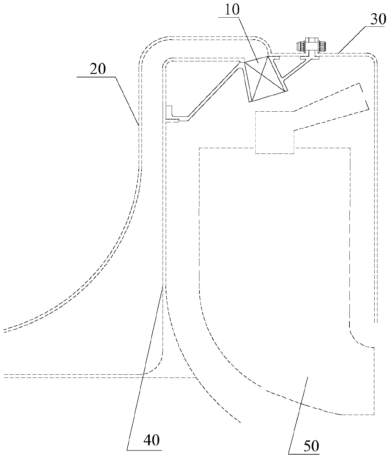
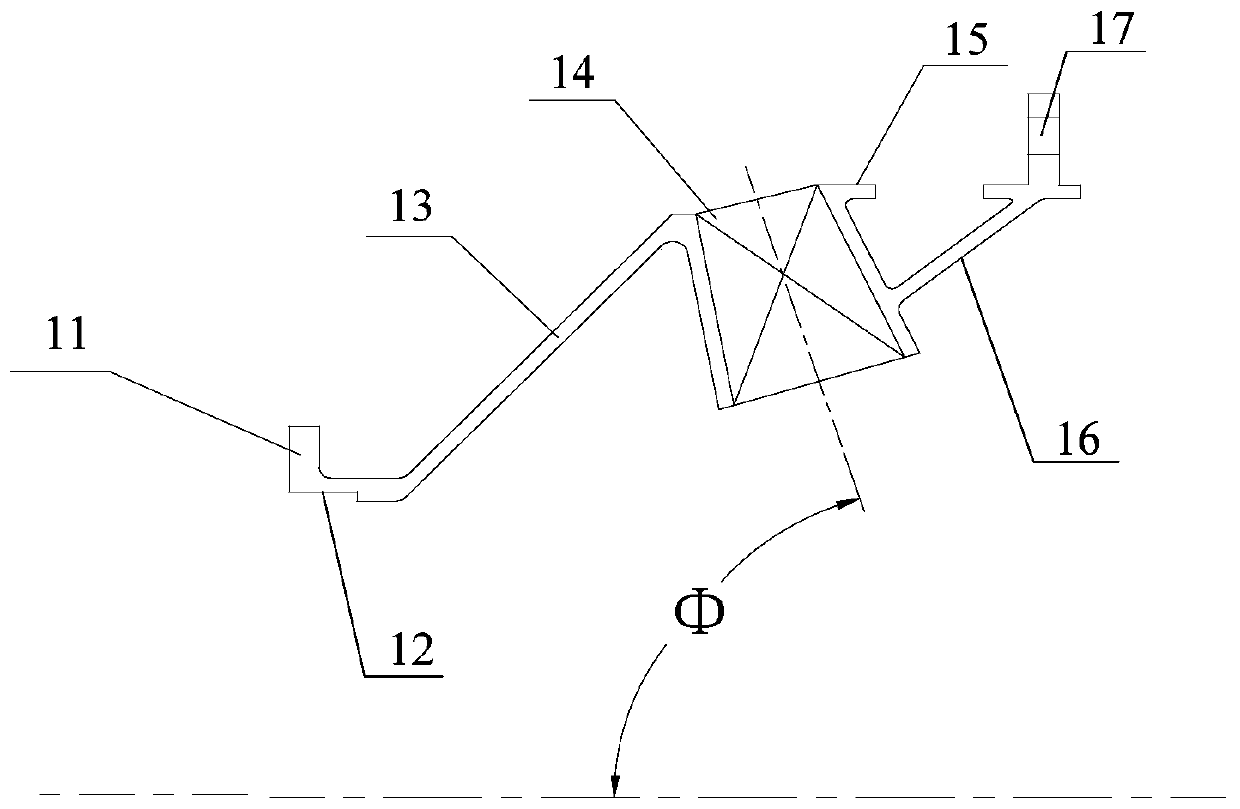
[0028] refer to Figure 2 to Figure 3 , the preferred embodiment of the present invention provides a diffuser for a radial flow combustor, because most of the existing diffusers are adapted to a direct-flow combustor or a recirculation combustor, and the exhaust gas of this diffuser The method is axial exhaust, but the radial airflow cannot be diffused and decelerated. Using the existing diffuser will cause inconsistent airflow speeds around the flame tube entering the combustion chamber, resulting in insufficient combustion, so that the combustion chamber is ineffective. Pressure loss increases. And the present invention is adapted to the diffuser of the radial flow combustion chamber, so th...


PUM


Abstract

The invention discloses a diffuser applicable to a radial flow combustor and a gas turbine. The diffuser is arranged at the outlet of a first air flow passage formed by an intermediate case and a centrifugal impeller cover and comprises a first support arm connected with the centrifugal impeller cover, a second support arm connected with the combustor casing, a plurality of guide vanes arranged between the first support arm and the second support arm and used for guiding inlet air and a second air flow passage formed among the plurality of guide vanes and used for diffusing and decelerating the inlet air; and the central axis of the second air flow passage is collinear with that of the combustor liner, so that air flowing out of the diffuser keeps an uniform velocity and equal pressure in the passages in front and rear of the combustor liner so as to avoid large-angle air flow turning. The diffuser applicable to the radial flow combustor and the gas turbine have the following benefits: on one hand, the total pressure loss of the combustor is reduced; on the other hand, air is easy to distribute to flow and be combusted in the combustor liner; besides, through the split type structural design of the diffuser, the processing is convenient, the disassembly and assembly is convenient, and the maintaining performance is good.

Description

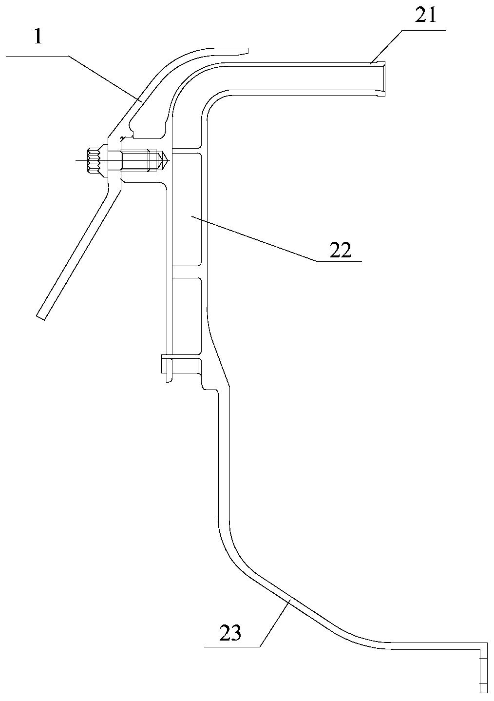
technical field [0001] The invention relates to the field of gas turbines, in particular to a radial flow combustor diffuser and a gas turbine. Background technique [0002] The diffuser is one of the key components in the combustion system. Its function is to reduce the airflow velocity from the compressor to facilitate the organization of combustion. The diffuser not only directly affects the performance of the combustion chamber, but also the performance of the engine. Reasonable design of diffuser is of great significance for improving combustion conditions, improving combustion chamber performance, and reducing combustion chamber size and weight. [0003] Such as figure 1 As shown in , in the prior art, the diffuser matched with the centrifugal compressor usually consists of two parts: "radial diffuser 22" and "axial diffuser 21". Realized in the sudden expansion area of ​​the outlet of the compressor 21; because the central axis of the existing diffuser outlet airfl...

Claims


Application Information

Patent Timeline
Patent Type & Authority Patents(China)
IPC IPC(8): F23R3/04
CPCF23R3/04
Inventor 曹俊王朝晖赵玉文陈剑郎旭东
Owner AECC HUNAN AVIATION POWERPLANT RES INST
Learn More