
Air-distribution fiber-ribbon-introduced cable

A technology of optical fiber ribbon and optical cable, which is applied in the field of aerial wiring to introduce optical fiber ribbon and optical cable, which can solve the problems of lack of support structure, inconsistent performance and reliability of the stripper, and inability to quickly strip the protective layer.

Active Publication Date: 2017-11-10
TIANJIN YOFC XMKJ OPTICAL CABLE +1
View PDF7 Cites 1 Cited by
  • Summary
  • Abstract
  • Description
  • Claims
  • Application Information

AI Technical Summary

Problems solved by technology

[0002] The optical cable is composed of multiple optical fibers and the outer protective layer for optical fiber protection. It has the superior performance of high safety and high reliability in signal transmission. The optical cable is usually laid overhead before installation and access. In the prior art, when the protective layer of the optical cable laid overhead is stripped, due to the different strength of the construction personnel and the different performance and reliability of the stripper, the protective layer cannot be quickly stripped, and sometimes the optical fiber at the stripped place will be damaged; the existing When the optical cable is laid overhead, because the optical cable itself lacks the main support structure, it mainly relies on the optical fiber and the thin steel wire close to the optical fiber to provide support. Such an optical cable lacks a certain structural strength, which is easy to cause the overall damage of the optical cable.

Method used


Image

  • Air-distribution fiber-ribbon-introduced cable
  • Air-distribution fiber-ribbon-introduced cable
  • Air-distribution fiber-ribbon-introduced cable

Examples


Embodiment Construction

[0027] It should be noted that, in the case of no conflict, the embodiments of the present invention and the features in the embodiments can be combined with each other.

[0028] In describing the present invention, it should be understood that the terms "center", "longitudinal", "transverse", "upper", "lower", "front", "rear", "left", "right", " The orientations or positional relationships indicated by "vertical", "horizontal", "top", "bottom", "inner" and "outer" are based on the orientations or positional relationships shown in the drawings, and are only for the convenience of describing the present invention and Simplified descriptions, rather than indicating or implying that the device or element referred to must have a particular orientation, be constructed and operate in a particular orientation, and thus should not be construed as limiting the invention. In addition, the terms "first", "second", etc. are used for descriptive purposes only, and should not be understood ...


PUM


Abstract

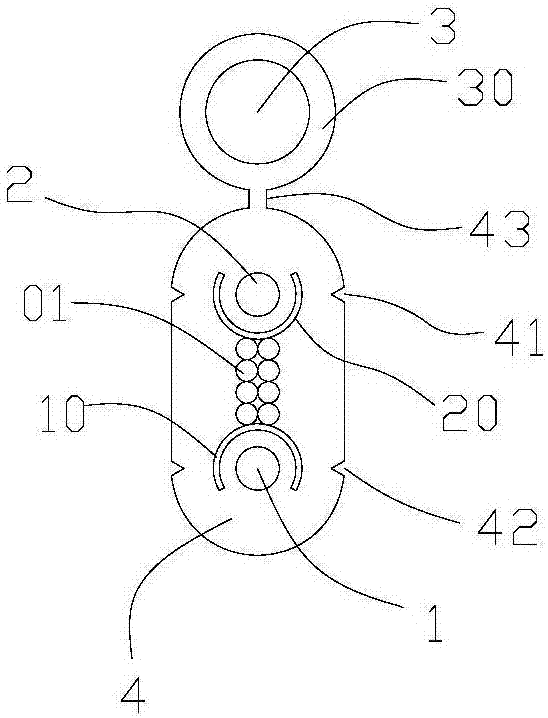
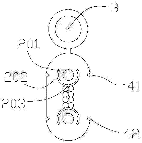
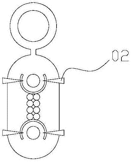
The invention provides an air-distribution fiber-ribbon-introduced cable comprising a first bearing unit, a second bearing unit, and fibers. A plurality of fibers are arranged between the first bearing unit and the second bearing unit. A first isolation part is arranged between the fibers and the first bearing unit; and a second isolation part is arranged between the fibers and the second bearing unit. The first isolation part and the second isolation part are in contact with the fibers. The first isolation part is separated from the first bearing unit; and the second isolation part is separated from the second bearing unit. Besides, a main protection layer coats the first bearing unit, the second bearing unit, the fibers, the first isolation part, and the second isolation part; and a first stripping positioning opening group and a second stripping positioning opening group that are arranged in pairs are arranged at positions corresponding to the first isolation part and the second isolation part outside the main protection layer. Therefore, the overall tensile strength of the cable is enhanced by 40%, so that the cable can be supported in an overhead manner effectively, the damage of the cable is reduced, and the cable erection cost is lowered. On the basis of the isolation part design, protection layer stripping of the cable is carried out conveniently.

Description

technical field [0001] The invention belongs to the field of optical cables, in particular to an aerial distribution lead-in optical fiber ribbon optical cable. Background technique [0002] The optical cable is composed of multiple optical fibers and the outer protective layer for optical fiber protection. It has the superior performance of high safety and high reliability in signal transmission. The optical cable is usually laid overhead before installation and access. In the prior art, when the protective layer of the optical cable laid overhead is stripped, due to the different strength of the construction personnel and the different performance and reliability of the stripper, the protective layer cannot be quickly stripped, and sometimes the optical fiber at the stripped place will be damaged; the existing When the optical cable is laid overhead, because the optical cable itself lacks the main support structure, it mainly relies on the optical fiber and the thin steel ...

Claims


Application Information

Patent Timeline
Patent Type & Authority Applications(China)
IPC IPC(8): G02B6/44
CPCG02B6/4409G02B6/4422G02B6/4439Y02A30/00
Inventor 苏日申孟宪杰李耀光赵远达
Owner TIANJIN YOFC XMKJ OPTICAL CABLE
Learn More