Spiral grinding machine for taper bushing

A grinding machine and grinding mechanism technology, applied in grinding machines, grinding/polishing equipment, grinding/polishing safety devices, etc., can solve problems affecting the health of operators and achieve the effect of reducing strength and improving discharge rate

Active Publication Date: 2019-01-22
CHONGQING SUTENG MACHINERY MFG
View PDF4 Cites 1 Cited by
  • Summary
  • Abstract
  • Description
  • Claims
  • Application Information

AI Technical Summary

Problems solved by technology

[0012] The object of the present invention is to provide a tapered bushing spiral grinding machine to solve the problem in the prior art that metal grinding floats in the air and affects the health of operators

Method used


Image

  • Spiral grinding machine for taper bushing
  • Spiral grinding machine for taper bushing

Examples


Embodiment

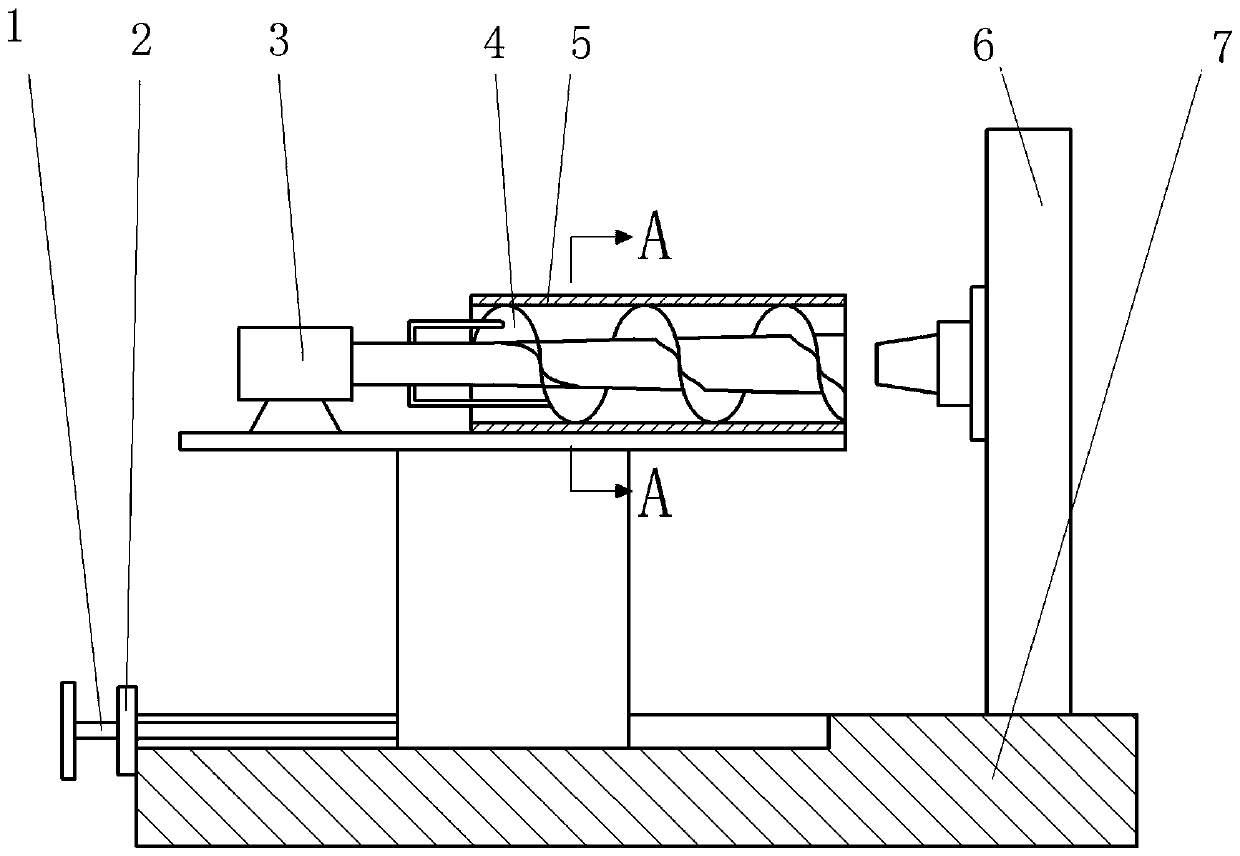
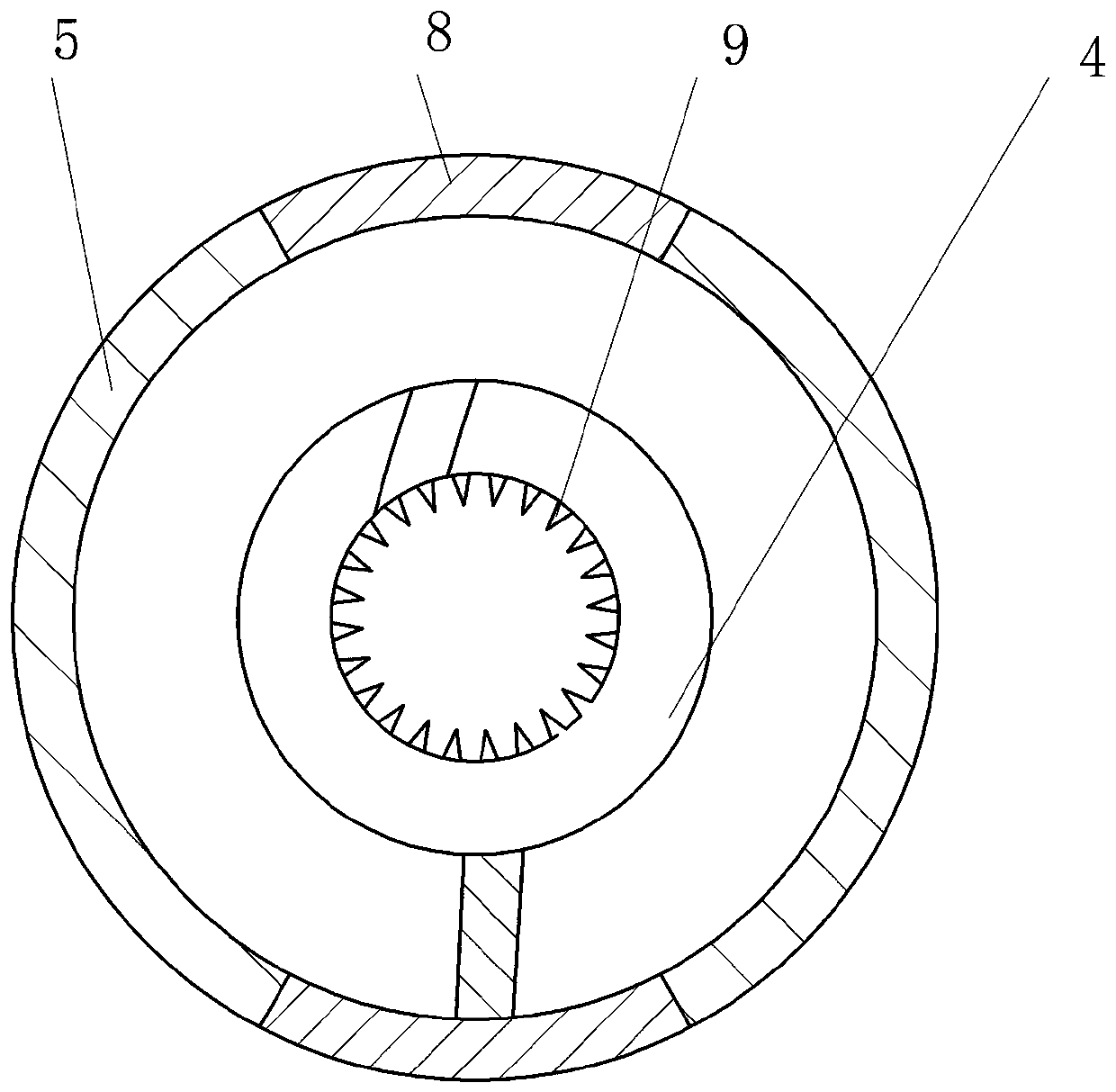
[0026] Embodiment: the taper shaft sleeve spiral grinding machine in this program, as figure 1 As shown, it includes a base 7, a feeding device, a grinding and fixing device and a tapered spiral grinding mechanism, and the feeding device, the tapered spiral grinding mechanism and the grinding and fixing device are arranged in sequence. The fixed shaft is processed with a thread matched with the internal thread of the tapered bushing, and the fixed shaft and the clamping seat 6 are integrally formed. The fixed shaft faces the large diameter end of the inner ring of the spiral blade, and the clamping seat 6 is threadedly fixed on the base 7 . The shell 5 is made of hard plastic, and the shell 5 is cylindrical. The shell 5 is screwed on the sliding seat, and the motor 3 is threaded on the sliding seat. The guide chute is integrally formed on the base 7, and the bottom of the sliding seat is integrally formed with a sliding part for sliding in the guide chute, and the sliding part...


PUM


Abstract

The invention belongs to the field of shaft sleeve machining and particularly discloses a spiral polishing machine for a taper shaft sleeve. The spiral polishing machine comprises a base, a feeding device, a polishing and fixing device and a taper spiral polishing mechanism, and the feeding device, the taper spiral polishing mechanism and the polishing and fixing device are arranged in sequence; the taper spiral polishing mechanism comprises a shell, a motor, a sliding seat and a shaftless spiral blade, the shell is of a barrel shape and is fixedly connected to the sliding seat, the motor is fixedly connected to the sliding seat, the base is provided with a guide sliding slot, the sliding seat is slidably connected into the guide sliding slot, and the shaftless spiral blade is located in the shell and fixedly connected to the output end of the motor; and the shell is made of magnets, the radius of the inner ring of the shaftless spiral blade is increased gradually in the axial direction, and the inner ring of the shaftless spiral blade is provided with a plurality of polishing particles. By means of the spiral polishing machine, the problem that in the prior art, metal abrasive dust floats in air and influences the health of operators is solved.

Description

technical field [0001] The invention belongs to the field of shaft sleeve processing. Background technique [0002] An existing shaft sleeve includes a first rod body, a second rod body, and a third rod body arranged coaxially, the second rod body is located between the first rod body and the third rod body, and the first rod body, the second rod body, and the third rod body The outer diameter of the rod body becomes larger successively, a chamfer is provided between the first rod body and the second rod body, a mounting hole is provided on the outer end surface of the third rod body, and the mounting hole extends into the first rod body, and a circle is provided at the bottom of the mounting hole. Shaped boss, at present, when processing this axle sleeve, its technology is complicated, and the reject rate of the axle sleeve after processing is high. [0003] The patent document whose authorized announcement number is CN105269259B discloses a processing method of a shaft sl...

Claims


Application Information

Patent Timeline
Patent Type & Authority Patents(China)
IPC IPC(8): B24B19/00B24B55/06
CPCB24B19/00B24B55/06
Inventor 王全中
Owner CHONGQING SUTENG MACHINERY MFG
Why Eureka
Try Eureka