
3D printing pen

A 3D printing pen and 3D printing technology, applied in 3D object support structures, additive manufacturing, coating devices, etc., can solve the problems of inconvenient handheld operation, troublesome maintenance work, complex product structure, etc., and improve the convenience of handheld operation , Easy maintenance and replacement work, to achieve the effect of maintenance and replacement work

Inactive Publication Date: 2017-11-17
CHANGSHA YUANDAHUA INFORMATION TECH CO LTD
View PDF1 Cites 1 Cited by
  • Summary
  • Abstract
  • Description
  • Claims
  • Application Information

AI Technical Summary

Problems solved by technology

[0002] The current hand-held 3D printing pens are mainly divided into two types: hot-melt type and light-curing type, and these two types of products currently on the market need to use electric devices to extrude 3D printing materials, which leads to complex product structures, many parts, The bulky size is not convenient for hand-held operation, there are many hidden troubles, the production process is complicated, and the manufacturing cost is high;
[0003] Currently, the 3D printing pens on the market use a single function of the nib, and they are all integrated designs. Therefore, the same 3D printing pen cannot meet the various creative needs of users at the same time, such as: handwriting thickness, handwriting shape, special functions of the nib, etc.
Moreover, if the pen head is damaged or blocked, the maintenance work will be very troublesome, and even the 3D printing pen will be scrapped;
[0004] The 3D printing pens currently on the market generally use linear 3D printing materials or injection 3D printing materials. The replacement of 3D printing materials during use will bring some troubles to users, or cause residual pollution inside the 3D printing pens that is difficult to clean And other issues

Method used


Image

  • 3D printing pen
  • 3D printing pen
  • 3D printing pen

Examples


Embodiment Construction

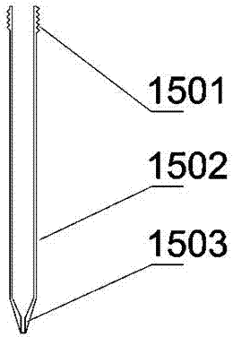
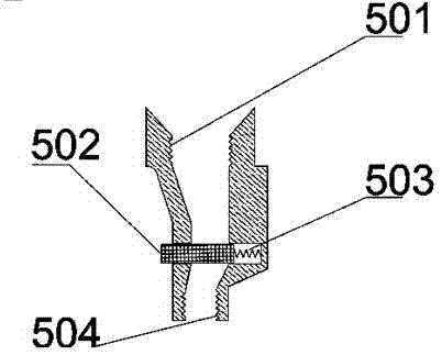
[0024] Such as figure 1 As shown, the 3D printing pen of the present invention includes a pen case and a nib 15 located at the front end of the pen case. The pen case includes an energy storage shell 2 and a 3D printing pen shell 9. The energy storage shell 2 and the 3D printing pen The pen housing 9 is connected by threads. A push rod 1 is movably installed in the energy storage shell 2 at the end of the pen case, and the tail of the push rod 1 protrudes outside the energy storage shell 2, and an energy storage spring 3 is installed on the push rod 1 in the energy storage shell 2, and the push rod 1 1 The head is provided with a piston 401, and extends into the printing material tank 4, such as Figure 4 As shown, the 3D printing material tank 4 is filled with 3D printing material 402 in the casing 403, and the head of the 3D printing material tank 4 is provided with a screw-type sealing installation interface 404. The head of the 3D printing material tank 4 is located at T...


PUM


Abstract

The invention relates to 3D printing technology, in particular to a 3D printing pen which comprises a pen shell and a pen point arranged at the front end of the pen shell, wherein the pen shell comprises an energy storage shell and a 3D printing pen shell; a pushing rod is movably mounted in the energy storage shell at the tail end of the pen shell; the tail part of the pushing rod stretches out of the energy storage shell; an energy storage spring is mounted on the pushing rod in the energy storage shell; the head of the pushing rod stretches into a printing material tank; and the head of the 3D printing material tank communicates with the pen point via a control valve in the 3D printing pen shell. The 3D printing pen, disclosed by the invention, is a novel handheld type 3D printing pen which can realize extrusion of 3D printing materials without adopting an electric device, and the pen points with different functions can be changed at will, so that the mechanical structure of the traditional handheld type 3D printing pen is greatly optimized, the difficulty of a production technology is lowered, the malfunction hidden danger of a traditional product is reduced and the manufacturing cost of the traditional product is greatly reduced.

Description

technical field [0001] The invention relates to 3D printing technology, in particular to a 3D printing pen. Background technique [0002] The current hand-held 3D printing pens are mainly divided into two types: hot-melt type and light-curing type, and these two types of products currently on the market need to use electric devices to extrude 3D printing materials, which leads to complex product structures, many parts, The bulky size is not convenient for hand-held operation, there are many hidden troubles, the production process is complicated, and the manufacturing cost is high; [0003] Currently, the 3D printing pens on the market use a single function of the nib, and they are all integrated designs. Therefore, the same 3D printing pen cannot meet the various creative needs of users at the same time, such as: handwriting thickness, handwriting shape, special functions of the nib, etc. . Moreover, if the pen head is damaged or blocked, the maintenance work will be very ...

Claims


Application Information

Patent Timeline
Patent Type & Authority Applications(China)
IPC IPC(8): B29C64/20B29C64/205B29C64/264B33Y30/00
CPCB33Y30/00
Inventor 郭志武
Owner CHANGSHA YUANDAHUA INFORMATION TECH CO LTD
Learn More