Printer external ink supply device

An ink supply device and printer technology, applied in printing, etc., can solve the problems of reducing the ink capacity of the external ink supply device of the printer, requiring extremely high processing precision in the light-transmitting area, and occupying the space of the ink chamber by the float, so as to simplify the external installation of the printer. The structure of the ink supply device, the effect of reducing the processing technology requirements and increasing the ink capacity

CN107351539AInactive Publication Date: 2017-11-17周利平
0 Cites 0 Cited by

Patent Information

Authority / Receiving Office
CN · China
Patent Type
Applications(China)
Current Assignee / Owner
Publication Date
2017-11-17
Estimated Expiration
Not applicable · inactive patent

Smart Images

  • Figure 1
    Figure 1
  • Figure 2
    Figure 2
  • Figure 3
    Figure 3
Patent Text Reader

Abstract

The invention relates to an external ink supply device for a printer, comprising a housing with a front wall, a top wall and a bottom wall, an ink outlet arranged at the lower part of the front wall, a first shielding part arranged at the upper part of the front wall, and The second shielding part on the outside of the middle part of the front wall, the light-transmitting part between the second shielding part and the front wall, is arranged on the housing and the third shielding part is located on the inside of the middle part of the front wall, and is arranged on the housing on the outer surface of the chip. Wherein, the chip includes a memory for storing ink remaining information and a communication part for communicating with the main board of the printer. The advantage is that the external ink supply device of the printer has a relatively simple structure, a high ink capacity, and the shell is easy to process.
Need to check novelty before this filing date? Find Prior Art

Description

technical field

[0001] The invention relates to an external ink supply device for an inkjet printer. Background technique

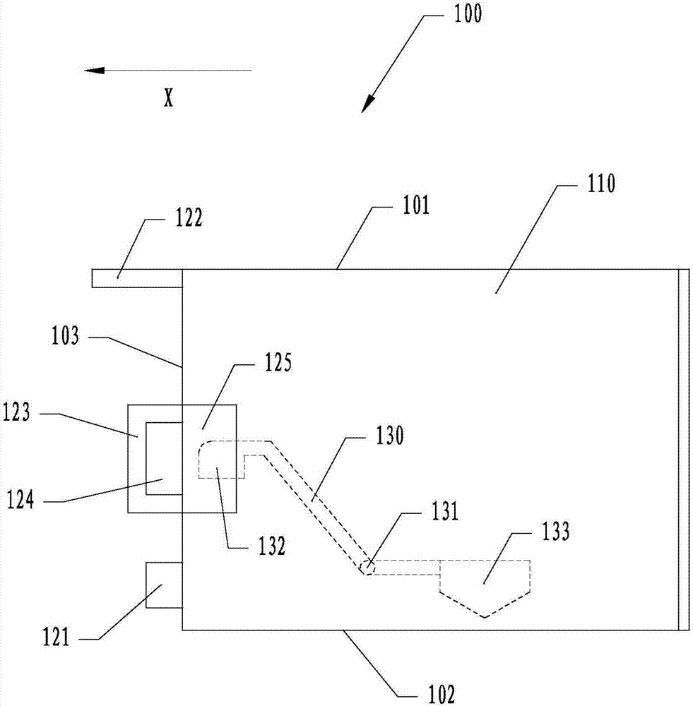
[0002] Such as figure 1 As shown, the direction X is the installation direction of the printer's external ink supply device 100 into the printer. The external ink supply device 100 of the printer has a casing 110 , and the casing 110 has a top wall 101 , a bottom wall 102 , and a front wall 103 . The lower part of the front wall 103 is provided with an ink outlet 121 , the upper part is provided with a first shielding part 122 , and the outer part of the middle part is provided with a second shielding part 123 . A light-transmitting portion 124 is disposed between the second shielding portion 123 and the front wall 103 , and a light-transmitting area 125 is disposed inside the middle of the front wall 103 . The first shielding part 122 is used to detect whether the ink supply device 100 external to the printer is installed properly. The thickness o...

Examples

Embodiment Construction

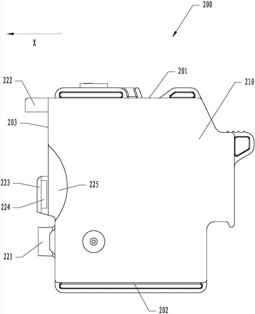
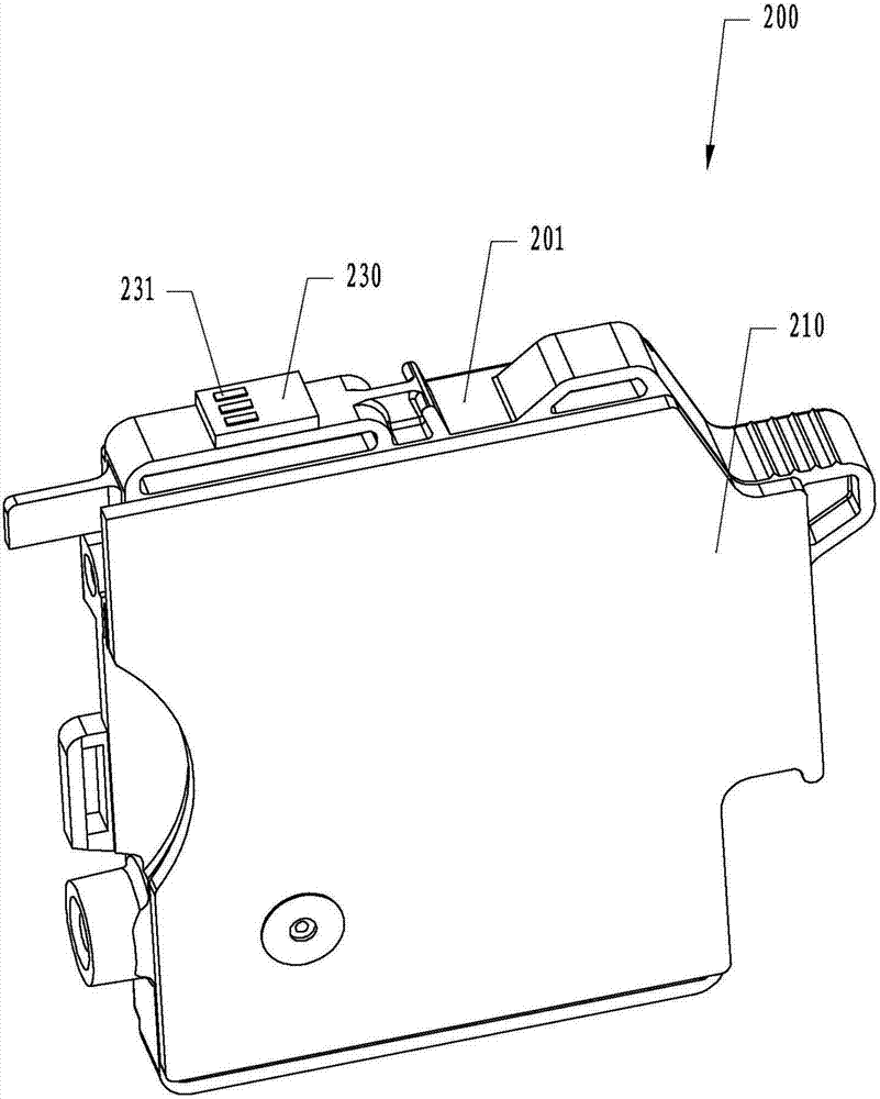
[0012] Such as figure 2 As shown, the direction X is the installation direction of the printer's external ink supply device 200 into the printer. The external ink supply device 200 of the printer has a casing 210 , and the casing 210 has a top wall 201 , a bottom wall 202 , and a front wall 203 . An ink outlet 221 is provided on the outside of the lower part of the front wall 203 , a first shielding part 222 is provided on the outside of the upper part, and a second shielding part 223 is provided on the outside of the middle part. A light-transmitting portion 224 is disposed between the second shielding portion 223 and the front wall 203 , and a third shielding portion 225 is disposed inside the middle of the front wall 203 . The first shielding part 222 is used to detect whether the ink supply device 200 external to the printer is installed in place. The thickness of the second shielding portion 223 along the direction X is used to determine the type of the ink supply dev...