Rotating transferring mechanism and lifting transferring machine with same

A technology of rotating mechanism and transfer machine, which is applied in the direction of conveyor objects, transportation and packaging, etc., can solve problems such as manual operation, and achieve the effect of good adaptability and good practicability.

Pending Publication Date: 2017-11-17
江苏艾伯赛精密机械有限公司
View PDF8 Cites 2 Cited by
  • Summary
  • Abstract
  • Description
  • Claims
  • Application Information

AI Technical Summary

Problems solved by technology

This method requires manual operation and is suitable for small workpieces; when it comes to large workpieces, it needs mechanized equipment to complete

Method used


Image

  • Rotating transferring mechanism and lifting transferring machine with same
  • Rotating transferring mechanism and lifting transferring machine with same
  • Rotating transferring mechanism and lifting transferring machine with same

Examples


Embodiment 1

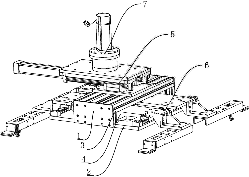
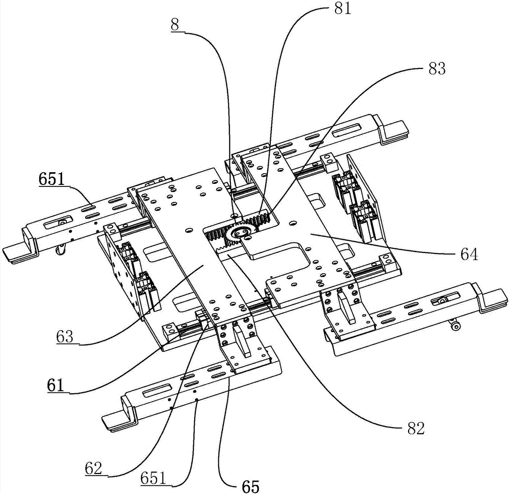
[0039] Embodiment 1: a kind of rotary transfer mechanism, such as figure 1 As shown, a mounting frame 1 is included, and the mounting frame 1 is composed of a base plate 2 and a "п" profile 3 arranged on the base plate 2, and a storage space 4 is formed between the "п" profile 3 and the base plate 2. An X-axis reciprocating mechanism 5 is provided above the "п" profile 3 of the mounting frame 1, and a Y-axis reciprocating mechanism 6 is provided in the storage space 4 of the mounting frame 1. The Y-axis reciprocating mechanism 6 passes through the "п" profile 3 and the X-axis The reciprocating mechanisms 5 are separated from each other, and a rotating mechanism 7 for interlocking the rotation of the X-axis reciprocating mechanisms 5 is provided on the upper side.

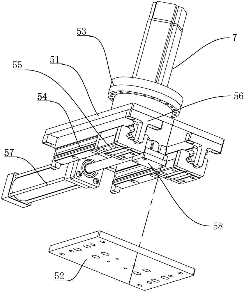
[0040] like figure 1 , figure 2As shown, the X-axis reciprocating mechanism 5 includes an upper support plate 51 linked with the rotation mechanism 7 and a lower support plate 52 fixed with the installation frame...

Embodiment 2

[0045] Embodiment 2: a kind of lifting transfer machine, such as Figure 5 As shown, it includes the installation arm 9 in the X direction, the lifting device 10 that the linkage installation arm 9 lifts along the Z axis, the rotating assembly 11 that the linkage lifting device 10 rotates, and the crawling device 12 that moves in the Y direction together with the linkage rotation assembly 11 and the lifting device 10 , the end of the mounting arm 9 is installed with the rotation transfer mechanism 13 in Embodiment 1, the rotation mechanism 7 is mounted on the mounting arm 9 and the rotation axis is the same as the Z axis.

[0046] like Figure 5 , Image 6 As shown, the crawling device 12 includes a casing 121 laid on the ground, a third linear slide rail 122 disposed on the casing 121 and a third slider 123 slidingly connected to the third linear slide rail 122, the third slide Block 123 is provided with seat plate 124, and rotating assembly 11 ( Image 6 has been disassem...


PUM


Abstract

The invention discloses a rotating transferring mechanism and a lifting transferring machine with the same. According to the technical scheme, the rotating transferring mechanism comprises multiple sucking disc sets, a rotating mechanism, an installation rack, an X-axis reciprocating mechanism and a Y-axis reciprocating mechanism, wherein the rotating mechanism enables the multiple sucking disc sets to rotate together in a linked manner along the Z axis, the installation rack is arranged between the sucking disc sets and the rotating mechanism and is rotated through the rotating mechanism in a linked manner, the X-axis reciprocating mechanism is linked with the rotating mechanism and pushes the installation rack to achieve horizontal reciprocating movement, and the Y-axis reciprocating mechanism is arranged in the installation rack and linked with the sucking disc sets for horizontal reciprocating movement. By means of the technical scheme, the sucking disc sets can achieve two-axis movement on the horizontal plane according to the X-axis reciprocating mechanism and the Y-axis reciprocating mechanism, and then the sucking disc sets are rotated through the rotating mechanism; and circumferential rotation of workpieces on sucking discs can be achieved according to the rotation point of the rotating mechanism, the rotation radius of the workpieces can be adjusted after rotation, and therefore the radial length from each workpiece to the rotation point can be adjusted so as to adapt to a needed position after the transferring process.

Description

technical field [0001] The invention relates to the field of automatic conveying devices, in particular to a rotary transfer mechanism and an elevating transfer machine equipped with the mechanism. Background technique [0002] On the automatic production line, the transfer and handling of workpieces is involved between multiple assembly lines. The enterprise arranges corresponding processing equipment at each process point on the assembly line, and uses operators to complete the transfer of workpieces. This method requires manual operation and is suitable for small workpieces; it requires mechanized equipment to complete large workpieces. [0003] At present, the Chinese patent with the notification number CN205060932U discloses a rotary transfer mechanism, including a rotary mechanism, a support that can be lifted up and down is arranged on the rotary mechanism, and several groups of suction cups are arranged at intervals on the support. The rotating mechanism includes a ...

Claims


Application Information

Patent Timeline
Patent Type & Authority Applications(China)
IPC IPC(8): B65G47/91
CPCB65G47/914
Inventor 陈炎华沈琪
Owner 江苏艾伯赛精密机械有限公司
Why Eureka
Try Eureka