Electronic lock and application of access control system of electronic lock

A technology of electronic locks and deadbolts, which is applied to building locks, locks controlled by non-mechanical transmission, buildings, etc., can solve the problems that electronic locks cannot be used universally, and the structure is complicated and inconvenient, and the structure is complicated, and achieves simple structure, strong versatility, The effect of ensuring safety

Pending Publication Date: 2017-11-17
佛山市奇点安防科技有限公司
View PDF5 Cites 4 Cited by
  • Summary
  • Abstract
  • Description
  • Claims
  • Application Information

AI Technical Summary

Problems solved by technology

Most of the motor mechanism drives the lock mechanism to move through the deceleration of the gear set, and the structure is complicated and inconvenient; the electromagnet releases the control point through magnetic action and opens the door.
The current electronic locks are not universal, and the structure is relatively complicated, so they can only be used on professional safes or lockers

Method used


Image

  • Electronic lock and application of access control system of electronic lock
  • Electronic lock and application of access control system of electronic lock
  • Electronic lock and application of access control system of electronic lock

Examples


Embodiment Construction

[0027] The present invention will be described in further detail below in conjunction with the accompanying drawings.

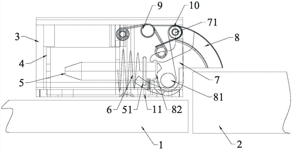
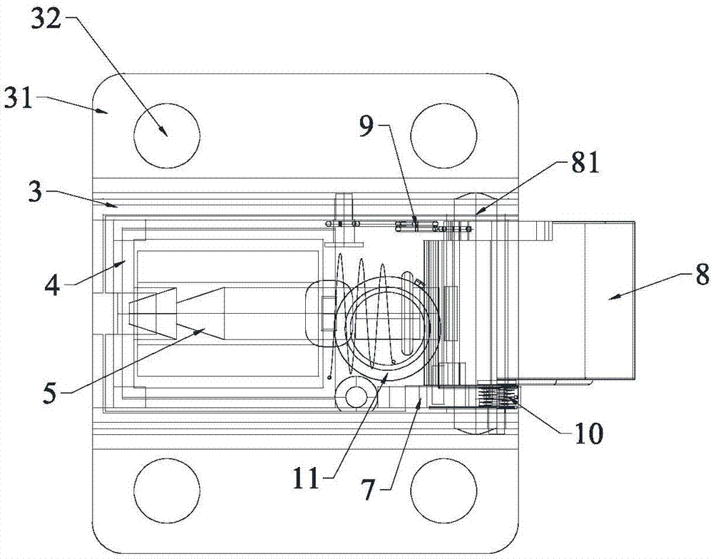
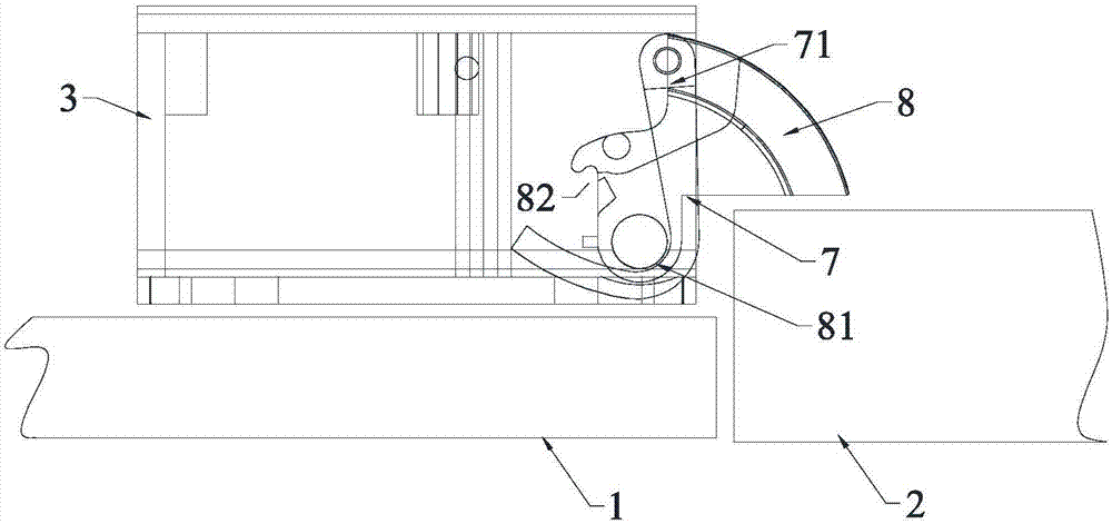
[0028] Figure 1-6 An electronic lock according to an embodiment of the present invention is schematically shown. As shown in the figure, the device is installed on the edge of the door body 1 through the lock box 3 , four fixing holes 32 are arranged on the lock box base 31 , and the lock box 3 is fixed on the door body 1 through the fixing holes 32 . The lock box 3 is provided with an electromagnet 5, a self-locking mechanism and a dead bolt 8. The electromagnet 5 is arranged on one side of the dead bolt 8, and the other side of the dead bolt 8 is correspondingly provided with a door frame 2.

[0029] Wherein, the lock box 3 is also provided with an electromagnetic seat 4, and the electromagnetic seat 4 is provided with an induction coil, and the induction coil is placed in the electromagnetic seat 4, which is simple and convenient, easy to install, and pr...


PUM


Abstract

The invention discloses an electronic lock and application of access control system of electronic lock and is mounted on the edge of the door body by a lock box. An electromagnet, a self-locking mechanism and a locking tab are provided in the lock box. The electromagnet is arranged on the one side of the locking tab. The other side of the locking tab is correspondingly provided with a door frame. One end of the self-locking mechanism is connected to one end of the locking tab. The other end of the self-locking mechanism is located in the lock box. The electromagnet can do back and forth movement relative to the locking tab. When the door opens, the electromagnet is controlled by electric power to move a certain distance away from the direction of the locking tab and is free from the restriction of the locking tab. When the door body is pulled, the door frame forces the locking tab to rotate at a certain angle in the forward direction of a first rotating shaft, and the door can be opened. Meanwhile, the self-locking mechanism rotates the lock box out with the opening angle of the door. When the door closes, the door frame first touches the self-locking mechanism. The self-locking mechanism rotates the front end of the self-locking mechanism and meets the tail of the locking tab. The locking tab is rotated through the first rotating shaft to complete the closing action. The electronic lock and the application of access control system of electronic lock have the advantages of simple structure, strong generality, safety and convenience.

Description

technical field [0001] The invention relates to the technical field of locks, in particular to an electronic lock and an access control system using the same. Background technique [0002] As early as more than 5,000 years ago, when private ownership in human society was produced, locks were also produced at the same time. The poet Mu Xin said, "If you lock it, people will understand it." It can be seen that locks are an indispensable tool for people's safety and privacy protection in life and work. With the development of science and technology in recent years, people have done a lot of research on the structure and mechanism of locks, and various locks and access control systems have emerged in an endless stream. [0003] At present, the locks sold on the market are mainly divided into two types: mechanical locks and electronic locks. The internal parts of the mechanical lock are mechanically connected, which is widely used in daily life. This kind of lock does not need t...

Claims


Application Information

Patent Timeline
Patent Type & Authority Applications(China)
IPC IPC(8): E05B47/02E05B15/00
CPCE05B15/00E05B47/0002E05B47/023
Inventor 李政一
Owner 佛山市奇点安防科技有限公司
Why Eureka
Try Eureka