Locking structure for impeller of high-speed magnetic-levitation fan

A fan impeller and locking structure technology, applied in mechanical equipment, machines/engines, liquid fuel engines, etc., can solve problems such as increased unbalance of the rotor system, poor centering accuracy, and reduced ability of the impeller to resist centrifugal load , to achieve the effect of less material loss, reliable locking and convenient disassembly and assembly

Inactive Publication Date: 2017-11-17
BEIHANG UNIV
View PDF10 Cites 8 Cited by
  • Summary
  • Abstract
  • Description
  • Claims
  • Application Information

AI Technical Summary

Problems solved by technology

The traditional fan impeller locking method is difficult to fully meet all the requirements of the appeal, and the structure is complex and difficult to process and assemble
[0003] Among the existing patents, the utility model patent CN201320089914.0 has the advantage of being easy to disassemble, but the structure is not suitable for high-speed centrifugal loads, and there is no centering method for the impeller and the rotor shaft.
In the structure described in the invention patent CN201210252876.6 and the utility model patent CN201220354231.9, the impeller is covered on the rotor shaft. As the speed increases, the fit gap between the impeller and the rotor shaft will become larger, resulting in a decrease in centering accuracy. Poor, the unbalance of the rotor system will also become larger
Moreover, there are many missing materials in the impeller core of this structure, which reduces the ability of the impeller to resist centrifugal load at high speed.
Although the structure of the magnetic levitation high-speed centrifuge described in the utility model patent CN201620271738.6 adopts the rod-type impeller locking method, it does not point out that the positioning method of the impeller and the rotor shaft is that the impeller is built in the rotor shaft, and only the impeller is built in the rotor. As the speed increases, the gap between the impeller and the rotor will not become larger
Moreover, it does not have an auxiliary torque transmission and anti-loosening device, which cannot guarantee stable torque transmission and reliable locking under high-speed, heavy-load and high-speed drop conditions.

Method used


Image

  • Locking structure for impeller of high-speed magnetic-levitation fan

Examples


Embodiment Construction

[0016] The present invention will be further described below in conjunction with the accompanying drawings and specific embodiments.

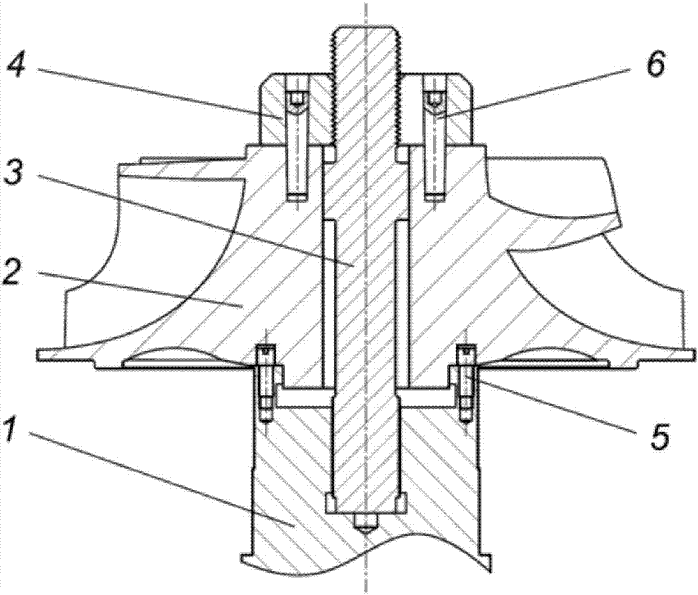
[0017] Such as figure 1 As shown, the high-speed maglev fan impeller locking structure of the present invention includes a rotor shaft 1 , an impeller 2 , a tie rod 3 , a nut 4 , a pin 5 , and a conical pin 6 . When installing, put the tie rod 3 into the screw hole at the end of the rotor shaft 1 until the bottom of the tie rod 3 touches the rotor shaft 1, install the pin 5 on the end of the rotor shaft 1, then install the impeller 2, and stretch the tie rod through the tensioner 3. After tightening the nut 4, use a drill bit to drill a hole on the impeller 2 through the hole reserved by the nut 4, and place the conical pin 6 with interference. When dismantling, firstly remove the conical pin 6 by a pin puller, then use a stretcher to elongate the pull rod 3 and then unscrew the nut 4, and finally remove the impeller 2, pull rod 3, and pin 5 s...


PUM


Abstract

The invention discloses a locking structure for an impeller of a high-speed magnetic-levitation fan. The locking structure for the impeller of the high-speed magnetic-levitation fan comprises a rotor shaft (1), the impeller (2), a pull rod (3), a nut (4), a dowel (5) and taper pin (6), wherein the lower end of the impeller (2) passes through the shaft surface to be arranged in an end hole of the rotor shaft, and the dowel (5) is arranged between the rotor shaft (1) and the impeller (2); the lower end of the pull rod (3) is connected with the rotor shaft (1) in a threaded mode, a step is arranged on the unthreaded rod portion of the pull rod (3) and matched with the impeller (2), and the upper end of the pull rod (3) is connected with the nut in a threaded mode; and the anti-loose taper pin (6) is arranged between the nut (4) and the impeller (2). By adoption of the locking structure, locking and looseness prevention can be ensured when the magnetic-levitation fan operates at a high speed, and meanwhile, the centering precision and stable torque transmission can be ensured when the impeller (2) operates. The locking structure for the impeller of the high-speed magnetic-levitation fan is compact, convenient to dismount and mount, reliable in locking and high in centering precision and can be widely applied to the field of high-speed magnetic-levitation fans.

Description

technical field [0001] The invention relates to the technical field of fan impeller locking, in particular to a high-speed magnetic levitation fan impeller locking structure, which can center, transmit torque, lock and prevent loosening of the impeller when the high-speed magnetic levitation fan turbine runs at high speed and with high stability role. Background technique [0002] High-speed magnetic levitation fans usually adopt a high-speed direct-drive arrangement, omitting the transmission system, and the impeller is directly installed on the rotor shaft end, so the installation method of the impeller is required to be detachable. And since the application of magnetic suspension bearings can reach very high operating speeds, the installation method of the impeller cannot reduce the strength of the impeller under centrifugal load. In addition, the control system of the magnetic bearing requires that the rotating system always maintain a high centering accuracy during ope...

Claims


Application Information

Patent Timeline
Patent Type & Authority Applications(China)
IPC IPC(8): F04D29/26F04D29/60
CPCF04D29/263F04D29/601
Inventor 刘刚董宝田王坤韩邦成郑世强
Owner BEIHANG UNIV
Why Eureka
Try Eureka