
Magnetic field cancellation big-current detection device and method

A technology of large current detection and magnetic field, applied in the direction of measuring device, only measuring current, voltage/current isolation, etc., can solve the problems of insufficient accuracy, unusable, large size of equipment, etc.

Active Publication Date: 2017-11-17
XI AN JIAOTONG UNIV
View PDF7 Cites 15 Cited by
  • Summary
  • Abstract
  • Description
  • Claims
  • Application Information

AI Technical Summary

Problems solved by technology

[0009] In order to solve the defects of the above-mentioned high-current measurement method, the patent 201610802270.3 adopts a dual-conductor magnetic field cancellation method, which can basically overcome the problems of large equipment size and insufficient accuracy caused by conventional high-current measurement.
But this method is only suitable for use in equipment such as switch cabinets. For power transmission and distribution lines, it cannot be used because it is unlikely to lay two parallel wires as required. High-current measurement solutions that can be used on the road

Method used


Image

  • Magnetic field cancellation big-current detection device and method
  • Magnetic field cancellation big-current detection device and method
  • Magnetic field cancellation big-current detection device and method

Examples


Embodiment

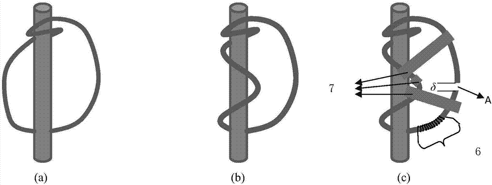
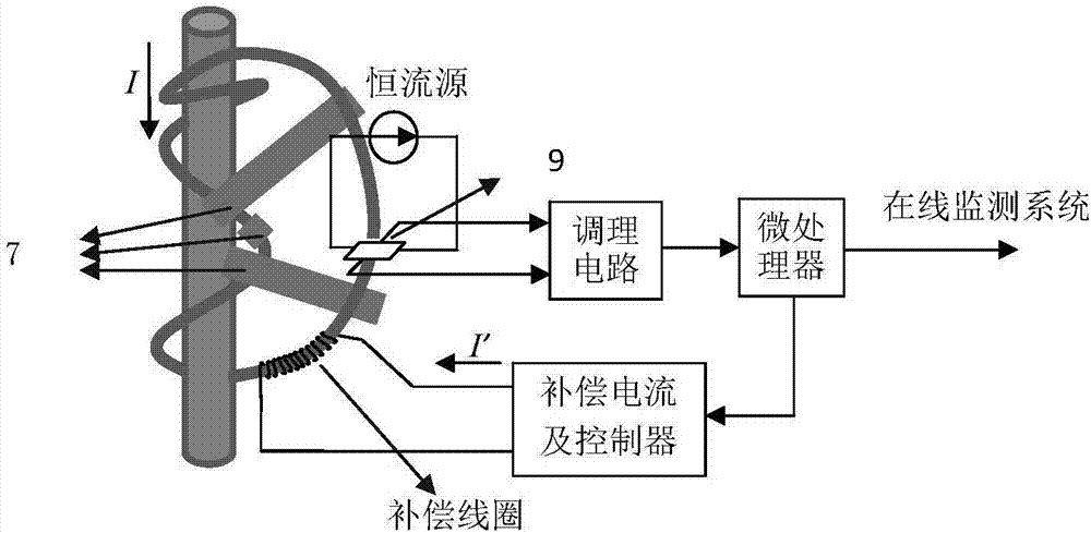
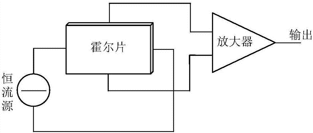
[0071] For the implementation of the direct current, for the convenience of illustration and discussion, this embodiment uses the Hall sensor as the detection unit to illustrate the implementation method of the patent of the present invention. Among them, the layout scheme of the current wire to be measured and the "concave" magnetic ring is as follows: figure 1 As shown, the system structure diagram of the measurement method is shown in figure 2 As shown, this detection device is composed of a magnetic ring of high magnetic permeability material, a Hall magnetic field sensor and its conditioning circuit, a microprocessor, a compensation coil, a compensation current and its controller, and a constant current source. On the measuring wire, fix it with a lock to form a "concave" magnetic ring with a notched air gap. A Hall magnetic field sensor is installed in the middle of the air gap, and a compensation coil is wound on the magnetic ring. The number of turns is N. 2 , Hall m...


PUM

PropertyMeasurementUnit
Winding angleaaaaaaaaaa

Abstract

The invention discloses a magnetic field cancellation big-current detection device and method. A to-be-detected current conductor is provided with two magnetic rings in a winding manner, wherein the winding angles of the two magnetic rings on the conductor are different, thereby forming a structure shaped similar to a concave structure. The intersection of the two magnetic rings is provided with a bigger gap, thereby enabling magnetic force lines to respectively form closed loops in the magnetic rings, and enabling the magnetic fields generated on the magnetic rings to be cancelled to leave a part of magnetic flux when a current passes through the conductor. The joint of the magnetic rings is provided with an air gap, and a magnetic field sensor is disposed at the air gap, and is used for detecting the remaining the magnetic flux. A voltage signal outputted by the magnetic field sensor is enabled to be zero through the adjustment of the current passing through a compensation coil wound around the magnetic rings. Because the remaining magnetic flux is smaller, the magnetic flux cannot be saturate in the magnetic rings, thereby enabling the whole measurement system to work in a linear region. The method can greatly reduce the size, weight and power consumption of the big-current measurement device, is high in accuracy, and is good in stability.

Description

Technical field: [0001] The invention relates to the fields of electrical engineering discipline, instrument science and technology, and to large current detection, in particular to a large current detection device and method for canceling the magnetic field of a magnetic ring. Background technique: [0002] The measurement method of large current is mainly divided into two categories: one is to determine the magnitude of the measured current according to the voltage drop generated by the measured current on the resistance, such as the shunt method; the other is based on the magnetic field formed by the measured current, Convert the current measurement problem to the magnetic field measurement problem, by measuring its magnetic flux, magnetic induction or magnetic potential, and then convert to obtain the magnitude of the current. The former has been difficult to meet the requirements of modern measurement due to the lack of volume, error, loss, insulation and measurement ra...

Claims


Application Information

Patent Timeline
IPC IPC(8): G01R19/00G01R15/18G01R15/20
CPCG01R15/185G01R15/202G01R15/207G01R19/0092
Inventor 汤晓君周生邱伟席磊磊刘帅
Owner XI AN JIAOTONG UNIV
Learn More