Power optimizer and control method and control device thereof

A technology of a power optimizer and a control method, which is applied in the output power conversion device, control/regulation system, conversion of DC power input to DC power output, etc. requirements and other issues to achieve the effect of improving overall efficiency

Active Publication Date: 2017-11-17
SUNGROW POWER SUPPLY CO LTD
View PDF4 Cites 15 Cited by
  • Summary
  • Abstract
  • Description
  • Claims
  • Application Information

AI Technical Summary

Problems solved by technology

[0005] This traditional working mode is based on the fact that the inductor L1 first stores energy and then releases energy in each switching cycle. The ripple current of the inductor L1 is very large, causing excessive core loss and conduction loss. At the same time Filtering pressure is also greater
In addit

Method used


Image

  • Power optimizer and control method and control device thereof
  • Power optimizer and control method and control device thereof
  • Power optimizer and control method and control device thereof

Examples


Embodiment Construction

[0068] The following will clearly and completely describe the technical solutions in the embodiments of the present invention with reference to the accompanying drawings in the embodiments of the present invention. Obviously, the described embodiments are only some, not all, embodiments of the present invention. Based on the embodiments of the present invention, all other embodiments obtained by persons of ordinary skill in the art without making creative efforts belong to the protection scope of the present invention.

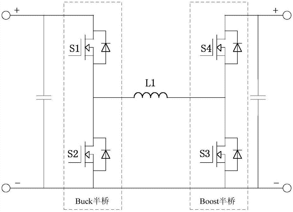
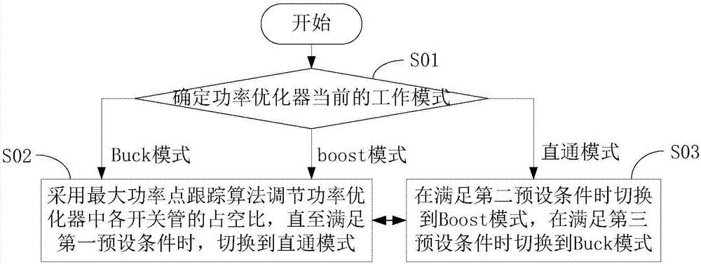
[0069] see figure 2 , the embodiment of the present invention discloses a power optimizer control method, including:

[0070] Step S01: Determine the current working mode of the power optimizer; among them, multiple working modes are set for the power optimizer in advance, and the multiple working modes include Buck mode, boost mode and direct mode, and the direct mode means that the input and output voltages are always equal working mode. If the power opti...


PUM


Abstract

The invention discloses a power optimizer and a control method and a control device thereof. The method comprises the following steps: determining a current working mode of the power optimizer, wherein the power optimizer is provided with a plurality of working modes in advance, the plurality of working modes comprising a Boost mode, a Buck mode and a direct mode; if the power optimizer works in the Boost mode or the Buck mode currently, adjusting duty ratio of each switching tube in the power optimizer through a maximum power point tracking algorithm until meeting a first preset condition, and then, switching to the direct mode; and if the power optimizer works in the direct mode currently, switching to the Boost mode when meeting a second preset condition and switching to the Buck mode when meeting a third preset condition, thereby improving efficiency of the power optimizer.

Description

technical field [0001] The present invention relates to the technical field of power electronics, and more specifically, relates to a power optimizer and its control method and control device. Background technique [0002] In the photovoltaic power generation system, the input side of multiple power optimizers is connected to independent photovoltaic modules, and the output side is connected to the DC bus in series. The power optimizer is used to realize the maximum power point tracking function of a single photovoltaic module. The main circuit topologies suitable for the power optimizer include full-bridge Buck-Boost circuit, Buck circuit, Boost circuit, etc. [0003] With the complexity of power optimizer applications, the traditional working mode of each main circuit topology can no longer meet the current working requirements. Next, take the full-bridge Buck-Boost circuit as an example to illustrate: [0004] The topology of the full-bridge Buck-Boost main circuit is a...

Claims


Application Information

Patent Timeline
IPC IPC(8): H02M3/158G05F1/67
CPCG05F1/67H02M3/1582
Inventor 杨宗军孔德鹏谢晶晶俞雁飞柏杨
Owner SUNGROW POWER SUPPLY CO LTD
Why Eureka
Try Eureka