
A Virtual Network Mapping Method Based on Optimizing Cost-Benefit Ratio

A technology of virtual network mapping and virtual network, which is applied in the field of large-scale virtual network mapping based on the optimized cost-benefit ratio, and can solve the problems of high mapping success rate and so on.

Active Publication Date: 2020-04-14
HARBIN INST OF TECH
View PDF4 Cites 0 Cited by
  • Summary
  • Abstract
  • Description
  • Claims
  • Application Information

AI Technical Summary

Problems solved by technology

[0003] The purpose of the present invention is to solve the shortcomings that the existing technology cannot guarantee a high mapping success rate within limited physical resources, and the existing technology mostly maps from a single virtual node to a single physical node, and proposes a method based on optimization overhead Virtual Network Mapping Method of Profit Ratio

Method used

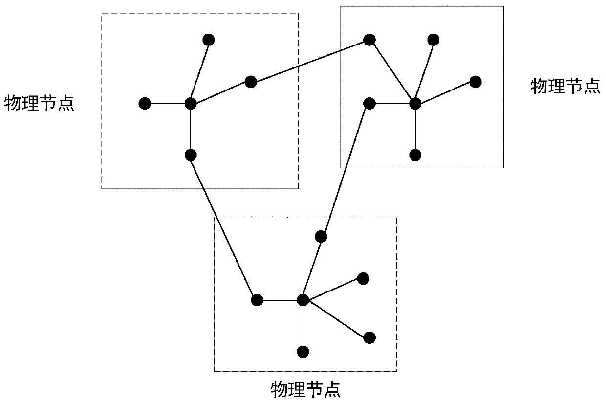
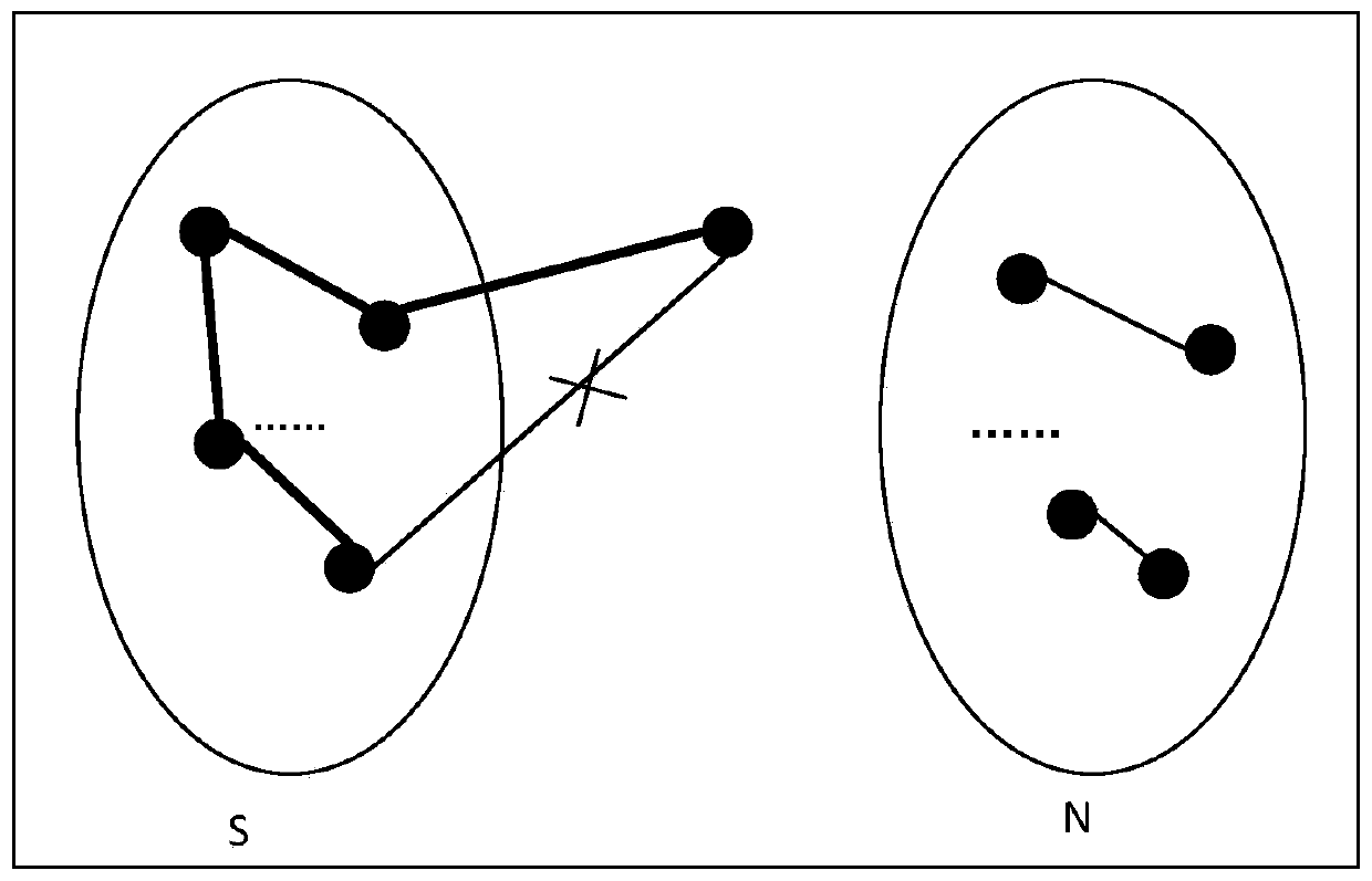

Image

  • A Virtual Network Mapping Method Based on Optimizing Cost-Benefit Ratio
  • A Virtual Network Mapping Method Based on Optimizing Cost-Benefit Ratio
  • A Virtual Network Mapping Method Based on Optimizing Cost-Benefit Ratio

Examples


specific Embodiment approach 1

[0023] Embodiment 1: A virtual network mapping method based on optimizing the cost-benefit ratio includes the following steps:

[0024] Step 1: Initialize the virtual network and the physical network, create the physical network sorting array PGAR[] and the virtual network sorting array VGR[], PGAR[] and VGR[] respectively represent the physical node array in the physical network and the virtual network in the virtual network array of nodes;

[0025] Step 2: Calculate the remaining resources of the physical nodes in PGAR[], and sort them from large to small;

[0026] Step 3: Calculate the resource requests of the virtual nodes in VGR[], and sort them from large to small;

[0027] Step 4: Calculate the initial quantity MergeCenterNum of virtual centers (referring to virtual nodes), and map the former MergeCenterNum virtual nodes of VGR[] to the former MergeCenterNum physical nodes of PGAR[] as virtual centers;

[0028] Step 5: For all non-virtual center nodes in the virtual n...

specific Embodiment approach 2

[0056] Specific embodiment two: the difference between this embodiment and specific embodiment one is: the specific process of calculating the remaining resource amount of the physical node in PGAR[] in the step two is:

[0057]

[0058] where AR v is the remaining resource amount of the physical node in PGAR[], FreeC(v) is the idle CPU resource of the physical node v, is the sum of link bandwidths connected to physical node v, E(v,u) is the link between physical nodes u connected to physical node v, E v is the set of all physical links connected to physical node v.

[0059] Other steps and parameters are the same as those in Embodiment 1.

specific Embodiment approach 3

[0060] Embodiment 3: The difference between this embodiment and Embodiment 1 or 2 is that the specific process of calculating the resource request amount of the virtual node in VGR[] in the step 3 is:

[0061]

[0062] where R i is the resource request amount of the virtual node in VGR[], C(i) is the CPU resource request amount of virtual node i, is the sum of link bandwidths connected to virtual node i, E(i,j) is the link between virtual node j connected to virtual node i, E i is the set of all virtual links connected to virtual node i.

[0063] Other steps and parameters are the same as those in Embodiment 1 or Embodiment 2.


PUM


Abstract

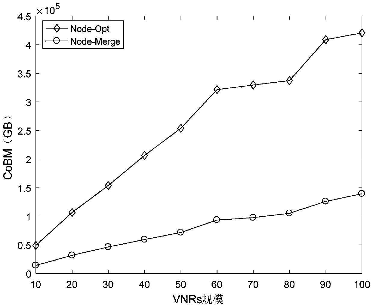
The invention relates to a virtual network mapping method based on an optimized ratio of cost to revenue. The invention relates to the virtual network mapping method, and aims to solve the problems that the prior art cannot ensure the high mapping success rate in limited physical resources and mapping from a single virtual node to a single physical node exists in most of the prior arts. The virtual network mapping method disclosed by the invention is as follows: the scale of a virtual network is enlarged in the existing virtual network mapping problem; therefore, the scale is greater than the scale of a bottom physical network; and namely, the node scale number of the virtual network is greater than that of the physical network. The virtual network mapping method disclosed by the invention mainly aims to reduce use of bottom physical resources as much as possible when all virtual network requests are mapped; and thus, the mapping success rate and the algorithm revenue of the method disclosed by the invention are increased. Compared with the traditional Node-Opt algorithm, the mapping revenue of the virtual network mapping method disclosed by the invention is increased by nearly 30%; the mapping success rate is generally increased by above 50% in different virtual network request scales; and the virtual network mapping method disclosed by the invention is used in the field of virtual network mapping.

Description

technical field [0001] The invention relates to the field of virtual network mapping, in particular to a large-scale virtual network mapping method based on optimizing cost-benefit ratio. Background technique [0002] With the rapid development of the modern Internet, storage technology, and network scale, computing resources have become cheaper, more powerful, and more ubiquitously available. This trend has led to the rapid development of cloud computing, a new computing model. The computing resources (cpu, storage) of this computing model are scattered in various data centers, and services are directly provided to users on demand, mainly in the form of VMs. These resources are more like a common accessory to use. The definition of network virtualization is to propose a potential solution to decompose the future network architecture into independent virtual networks. These networks independently undertake the network services of various customers, and these virtual network...

Claims


Application Information

Patent Timeline
Patent Type & Authority Patents(China)
IPC IPC(8): H04L12/24G06F9/455G06F9/54
CPCG06F9/45533G06F9/45558G06F9/546G06F2009/45595H04L41/0823H04L41/0896H04L41/12H04L41/145
Inventor 张伟哲王德胜李雄何慧刘亚维
Owner HARBIN INST OF TECH
Learn More