
Ultrasonic imaging method and system and ultrasonic imaging equipment

An imaging method and imaging system technology, applied in ultrasonic/sonic/infrasonic diagnosis, ultrasonic/sonic/infrasonic Permian technology, ultrasonic/sonic/infrasonic image/data processing, etc. Check the frame rate and display frame rate, affect the detection of intervening objects, etc., to avoid the low quality of reflected signals, improve the detection effect, and improve the imaging quality

Active Publication Date: 2017-11-21
SONOSCAPE MEDICAL CORP
View PDF4 Cites 5 Cited by
  • Summary
  • Abstract
  • Description
  • Claims
  • Application Information

AI Technical Summary

Problems solved by technology

[0003] Ultrasonic beams are emitted to the intervention at several deflection angles to form multiple frames of image data, which affects the scanning frame rate and display frame rate to a certain extent, and the fixed deflection angle cannot guarantee that it is perpendicular or close to the intervention. achieve the best results
At the same time, limited by the deflection capability of the probe, it is difficult to guarantee the quality of the deflection reflection signal
Affects the detection of intervening objects, resulting in low image quality

Method used


Image

  • Ultrasonic imaging method and system and ultrasonic imaging equipment
  • Ultrasonic imaging method and system and ultrasonic imaging equipment
  • Ultrasonic imaging method and system and ultrasonic imaging equipment

Examples


Embodiment Construction

[0069] The following will clearly and completely describe the technical solutions in the embodiments of the present invention with reference to the accompanying drawings in the embodiments of the present invention. Obviously, the described embodiments are only some, not all, embodiments of the present invention. Based on the embodiments of the present invention, all other embodiments obtained by persons of ordinary skill in the art without making creative efforts belong to the protection scope of the present invention.

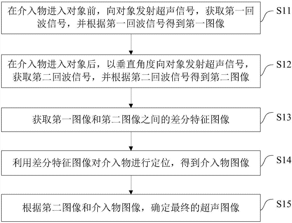
[0070] The embodiment of the present invention discloses an ultrasonic imaging method, see figure 1 As shown, the method includes:

[0071] Step S11: before the intervention object enters the object, transmit an ultrasonic signal to the object, obtain a first echo signal, and obtain a first image according to the first echo signal.

[0072] In the actual application process, the processes of transmitting ultrasonic signals and obtaining corresponding echo sig...


PUM


Abstract

The invention discloses an ultrasonic imaging method and system and ultrasonic imaging equipment. The method comprises the steps of transmitting an ultrasonic signal to an object before an intervening object enters the object to obtain a first echo signal, and obtaining a first image according to the first echo signal; transmitting an ultrasonic signal to the object at a perpendicular angle after the intervening object enters the object to obtain a second echo signal, and obtaining a second image according to the second echo signal; obtaining a difference characteristic image between the first image and the second image; utilizing the difference characteristic image to locate the intervening object to obtain an image of the intervening object; determining a final ultrasonic image according to the second image and the image of the intervening object. According to the ultrasonic imaging method and system and the ultrasonic imaging equipment, in the process of locating the intervening object, a deflection angle does not need to be preset, what is only needed is to maintain that condition that the ultrasonic signal is transmitted at the perpendicular angle, therefore the problem that the quality of the echo signals is low due to the preset deflection angle is avoided, the locating precision of the intervening object is improved, and the detection effect of the intervening object is improved.

Description

technical field [0001] The invention relates to the technical field of ultrasonic imaging, in particular to an ultrasonic imaging method, system and ultrasonic imaging equipment. Background technique [0002] In current ultrasonic diagnostic equipment, most of them use a single vertical angle and several deflection angles to transmit ultrasonic beams to intervention objects such as puncture needles, so as to obtain vertical frame and several deflection frame reflection signals. Several deflection angles are generally adopted to be perpendicular or nearly perpendicular to the insertion angle of the intervention to achieve the purpose of enhancing ultrasound reflection. [0003] Ultrasonic beams are emitted to the intervention at several deflection angles to form multiple frames of image data, which affects the scanning frame rate and display frame rate to a certain extent, and the fixed deflection angle cannot guarantee that it is perpendicular or close to the intervention. ...

Claims


Application Information

Patent Timeline
IPC IPC(8): A61B8/08
CPCA61B8/085A61B8/52
Inventor 陈伟璇冯乃章
Owner SONOSCAPE MEDICAL CORP
Learn More