An intelligent high-efficiency dust removal device and its working method

A technology of dust removal equipment and working methods, which is applied in the direction of chemical instruments and methods, separation methods, and separation of dispersed particles, which can solve the problems of high cost and general dust removal effect, and achieve the effects of improved effect, easy implementation, and simple structure

Inactive Publication Date: 2020-02-11
太仓市除尘设备厂
View PDF5 Cites 1 Cited by
  • Summary
  • Abstract
  • Description
  • Claims
  • Application Information

AI Technical Summary

Problems solved by technology

[0003] Most of the existing dust removal equipment on the market use fans or electrostatic dust collectors. During the working process, the dust removal effect is average, and the discharged gas will still be mixed with a lot of particles, and some large-scale dust removal equipment has the best dust removal effect in time. Very good, but its cost is high, so the existing dust removal equipment needs to be improved

Method used


Image

  • An intelligent high-efficiency dust removal device and its working method
  • An intelligent high-efficiency dust removal device and its working method

Examples


Embodiment 1

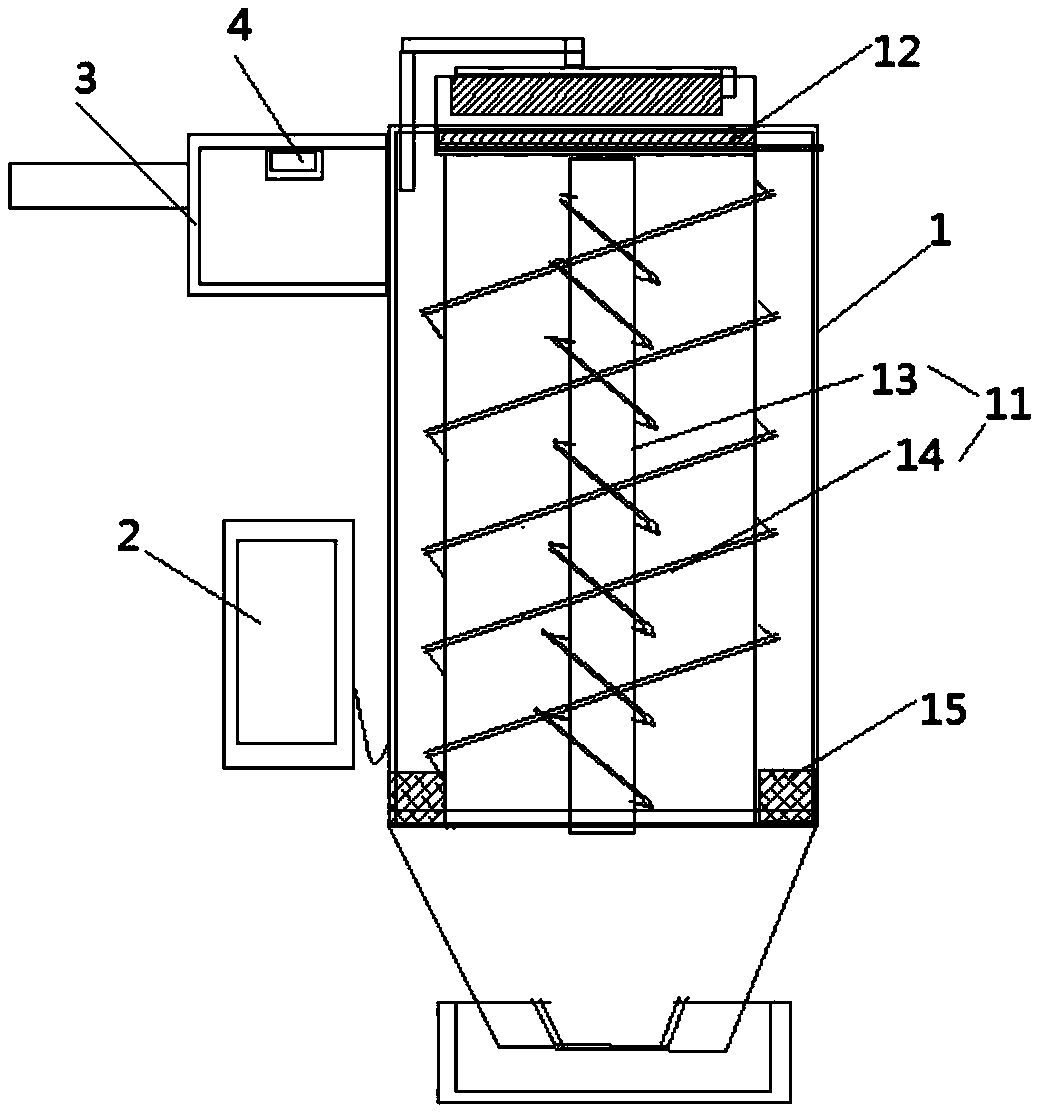
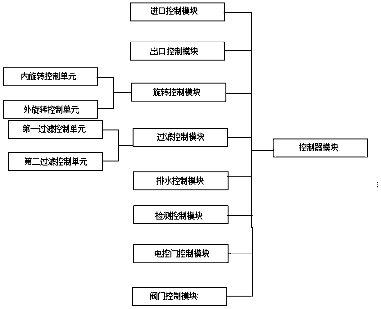
[0039] A working method of intelligent high-efficiency dust removal equipment as shown in the figure, wherein the intelligent high-efficiency dust removal equipment includes: a housing 1 and a control device 2, the housing 1 is provided with a group of air inlets and an air outlet, the The air inlet is provided with a gas collection chamber 3, and the inside of the housing 1 is provided with a rotating mechanism 11 and a first filter mechanism 12, and the rotating mechanism 11 is provided with an inner rotating mechanism 13 and an outer rotating mechanism 14, and the inner rotating mechanism The mechanism 13 and the external rotation mechanism 14 are arranged in opposite directions. The first filter mechanism 12 is provided with the outlet of the internal rotation mechanism 13. The gas collection chamber 3 is provided with a gas detection mechanism 4. The rotation mechanism 11, the second A filter mechanism 12 and the gas detection mechanism 4 are both connected to the control de...

Embodiment 2

[0049] A working method of intelligent high-efficiency dust removal equipment as shown in the figure, wherein the intelligent high-efficiency dust removal equipment includes: a housing 1 and a control device 2, the housing 1 is provided with a group of air inlets and an air outlet, the The air inlet is provided with a gas collection chamber 3, and the inside of the housing 1 is provided with a rotating mechanism 11 and a first filter mechanism 12, and the rotating mechanism 11 is provided with an inner rotating mechanism 13 and an outer rotating mechanism 14, and the inner rotating mechanism The mechanism 13 and the external rotation mechanism 14 are arranged in opposite directions. The first filter mechanism 12 is provided with the outlet of the internal rotation mechanism 13. The gas collection chamber 3 is provided with a gas detection mechanism 4. The rotation mechanism 11, the second A filter mechanism 12 and the gas detection mechanism 4 are both connected to the control ...


PUM


Abstract

The invention discloses a working method of intelligent high-efficiency dust removal equipment. The intelligent high-efficiency dust removal equipment includes: a housing and a control device, an air inlet is provided with a gas collection chamber, and the inside of the housing is provided with a rotating mechanism and a first filtering mechanism. The rotating mechanism is provided with an inner rotating mechanism and an outer rotating mechanism, and the inner rotating mechanism and the outer rotating mechanism are arranged in opposite directions. The mechanism, the first filter mechanism and the gas detection mechanism are all connected with the control device. The present invention sets a gas collection chamber at the air inlet, detects the impurity content and concentration in the gas through the gas detection mechanism, and judges the time and frequency of dust removal according to the detection result. The external rotation mechanism allows it to form an external vortex and an internal vortex, using natural gravity to achieve double separation, and then perform deep filtration through the filter mechanism.

Description

technical field [0001] The invention belongs to the field of dust removal equipment, and in particular relates to an intelligent high-efficiency dust removal equipment and a working method thereof. Background technique [0002] With the rapid development of social economy, people's living standards and quality of life are constantly improving, and whether it is production or life, people's rhythm is constantly accelerating, and most of them have realized intelligence and automation in both production and life. , and the quality requirements for the environment are getting higher and higher, which promotes the generation of dust removal equipment. [0003] Most of the existing dust removal equipment on the market use fans or electrostatic dust collectors. During the working process, the dust removal effect is average, and the discharged gas will still be mixed with a lot of particles, and some large-scale dust removal equipment has the best dust removal effect in time. Very ...

Claims


Application Information

Patent Timeline
Patent Type & Authority Patents(China)
IPC IPC(8): B01D50/00
CPCB01D50/10
Inventor 陆维光
Owner 太仓市除尘设备厂
Why Eureka
Try Eureka