Automobile part punching equipment

A technology of auto parts and punching, which is applied in the field of parts manufacturing, can solve the problems of troublesome parts picking and high manual labor intensity, and achieve the effects of convenient quality inspection, improving punching efficiency and reducing labor intensity

Active Publication Date: 2017-11-21
CHONGQING YOUBO MACHINERY MFG
View PDF6 Cites 3 Cited by
  • Summary
  • Abstract
  • Description
  • Claims
  • Application Information

AI Technical Summary

Problems solved by technology

Although this method properly improves the punching efficiency, it is cumbersome to take out the parts, and the waste generated after punching needs to be removed. The efficiency needs to be further improved, and the labor intensity is high.

Method used


Image

  • Automobile part punching equipment
  • Automobile part punching equipment
  • Automobile part punching equipment

Examples


Embodiment Construction

[0015] The present invention will be described in further detail below by means of specific embodiments:

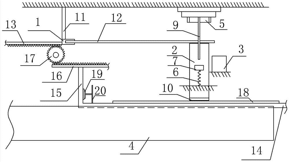
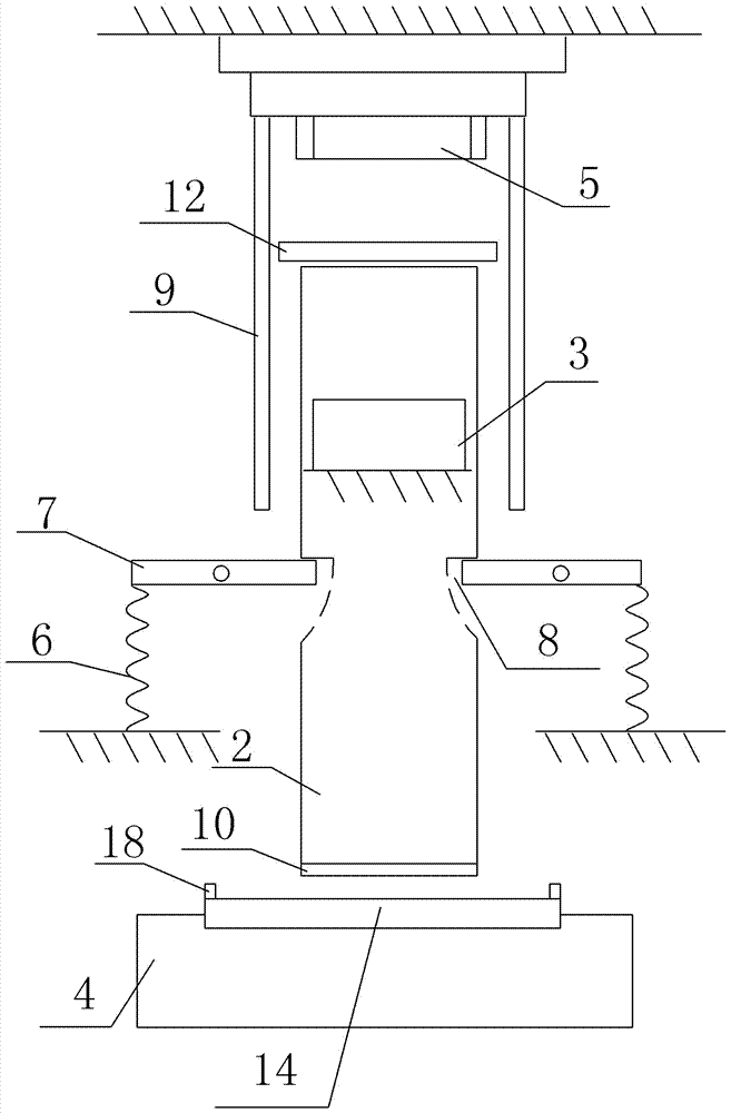
[0016] The reference signs in the drawings of the description include: clamping pliers 1, lower mold 2, waste box 3, base 4, punch 5, extension spring 6, support bar 7, card slot 8, pressing rod 9, rubber pad 10 , slide bar 11, steel plate 12, first rack 13, horizontal transfer plate 14, vertical transfer plate 15, second rack 16, gear 17, baffle plate 18, cylinder 19, push plate 20.

[0017] Such as figure 1 The punching equipment for auto parts shown includes a punching machine, a servo motor, a clamp 1 , a cylindrical lower mold 2 , a waste box 3 , two supporting mechanisms, a transfer plate and a base 4 . The servo motor and the punching machine are connected in series through the controller, and the controller is used to control the start and stop of the servo motor and the punching machine. The punching machine is fixed on the frame, and the punching machine incl...


PUM


Abstract

The invention relates to the field of part manufacturing, in particular to automobile part punching equipment. The automobile part punching equipment comprises a punch, a lower die, a servo motor, a pair of clamp pincers, a conveying plate, a waste tank and supporting mechanisms. The clamp pincers are slidably connected to a machine frame and connected with a first rack. The conveying plate is slidably connected with a base. A second rack is connected to the conveying plate. An output shaft of the servo motor is fixedly connected with a gear. The gear is engaged with the first rack and the second rack simultaneously. Each supporting mechanism comprises a tension spring and a supporting bar. The supporting bars are hinged to the machine frame. One ends of the tension springs are fixedly connected with the machine frame. The free ends of the tension springs are fixedly connected with one ends of the corresponding supporting bars. The peripheral wall of the lower die is provided with clamping grooves matched with the other ends of the supporting bars. Pressing rods are fixed to the punch. The lower ends of the pressing rods are aligned with the ends, close to the lower die, of the supporting bars. The waste tank is fixed to the machine frame and located on one side of the lower die. The servo motor and a punch press are connected through a controller in series. By means of the technical scheme, the automobile part punching equipment can automatically take parts and automatically collect waste materials.

Description

technical field [0001] The invention relates to the field of accessory manufacturing, in particular to punching equipment for auto accessories. Background technique [0002] Such as image 3 The ring-shaped auto parts shown are generally punched and formed. Traditional punching is to put a single piece of steel plate on the cylindrical lower mold, and the circular upper mold punches the steel plate and then removes the steel plate, and then removes the punched circular auto parts and the waste produced by punching. Classification under the bottom; due to the characteristics of a round hole in the middle of the ring-shaped auto parts, the ring-shaped auto parts after punching will be set on the cylindrical lower mold, and the lower mold is fixedly connected with the base. Ring-shaped auto parts cannot fall automatically, and it is troublesome to pick up the parts, and the punching efficiency is low. In order to save the time for picking up parts, most of the current punchin...

Claims


Application Information

Patent Timeline
IPC IPC(8): B21D28/34B21D28/26B21D43/11B21D43/20B21C51/00
CPCB21C51/00B21D28/26B21D28/34B21D43/11B21D43/20
Inventor 陈明友
Owner CHONGQING YOUBO MACHINERY MFG
Why Eureka
Try Eureka