Cantilever type soldering machine

A soldering machine and cantilever-type technology, which is applied in the direction of tin feeding device, welding equipment, auxiliary device, etc., can solve the problems of poor positioning accuracy of circuit boards, high labor costs, and poor assembly effect of circuit boards.

Inactive Publication Date: 2017-11-21
DONGGUAN OKATA ELECTRONICS & TECH
View PDF0 Cites 8 Cited by
  • Summary
  • Abstract
  • Description
  • Claims
  • Application Information

AI Technical Summary

Problems solved by technology

[0002] As we all know, the installation of circuit boards requires soldering. Traditionally, soldering of circuit boards is done by hand. Manual soldering of circuit boards is not only labor-intensive, high labor cost, poor welding accuracy and low welding efficiency, but also The assembly effect of the circuit board is poor, and the yield rate is low. Later, some semi-automatic soldering machines appeared on the market. Although they can solder the circuit board, their soldering iron tip cannot be adjusted, and it can only be used for the circuit board on the horizontal plane. Solder and it can only solder one circuit board at a time, resulting in poor positioning accuracy of the circuit board and the soldering machine is not working when loading and unloading the circuit board. It still cannot overcome the soldering of the circuit board. Problems of low efficiency, low yield and poor operational flexibility

Method used


Image

  • Cantilever type soldering machine
  • Cantilever type soldering machine
  • Cantilever type soldering machine

Examples


Embodiment Construction

[0018] In order to facilitate the understanding of the present invention, the present invention will be described more fully below with reference to the associated drawings. Preferred embodiments of the invention are shown in the accompanying drawings. However, the present invention can be embodied in many different forms and is not limited to the embodiments described herein. On the contrary, the purpose of providing these embodiments is to make the disclosure of the present invention more thorough and comprehensive.

[0019] Unless otherwise defined, all technical and scientific terms used herein have the same meaning as commonly understood by one of ordinary skill in the technical field of the invention.

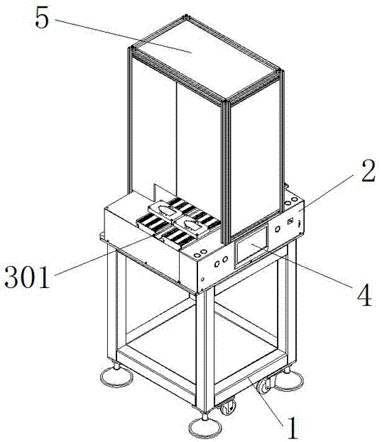
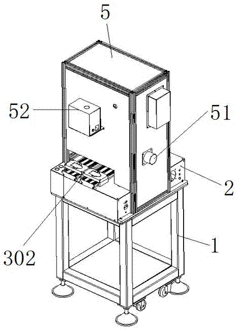
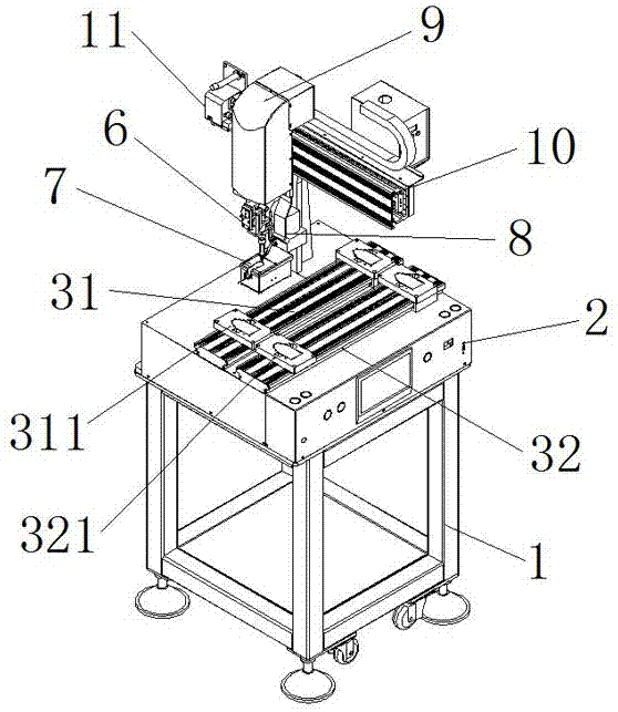
[0020] In this example, refer to Figure 1 to Figure 6 As shown, the cantilever type soldering machine of the present invention includes a frame 1, an electric control box 2 is arranged on the top of the frame 1, and first Y-direction slide rails 31 and first Y-directio...


PUM


Abstract

The cantilever type soldering machine of the present invention includes a frame, an electric control box, a first Y-direction slide rail, a second Y-direction slide rail, a front feeding station, a rear feeding station, an operating touch screen, an outer cover, and a smoke exhaust port , temperature controller, first circuit board component fixture, second circuit board component fixture, soldering iron head mechanism, automatic cleaning tin slag box, smoke hood, Z-direction slide rail, X-direction slide rail and tin feeder. The invention can realize fully automatic feeding, conveying and positioning of the circuit board and the horizontal, vertical and vertical adjustment and positioning of the soldering iron tip mechanism, and can perform angle adjustment and positioning of the soldering iron tip mechanism, so that the soldering iron tip mechanism can The circuit board can be soldered and positioned from different directions and different angles. Its soldering precision and soldering efficiency are high. During its operation, the product is placed at the front feeding station, and the product is taken at the rear, which can reduce the traditional Each station must be specially equipped with workers who pick and place products, thereby reducing the labor cost of workers and increasing production capacity.

Description

technical field [0001] The invention relates to a cantilever type soldering machine. Background technique [0002] As we all know, the installation of circuit boards requires soldering. Traditionally, soldering of circuit boards is done by hand. Manual soldering of circuit boards is not only labor-intensive, high labor cost, poor welding accuracy and low welding efficiency, but also The assembly effect of the circuit board is poor, and the yield rate is low. Later, some semi-automatic soldering machines appeared on the market. Although they can solder the circuit board, their soldering iron tip cannot be adjusted, and it can only be used for the circuit board on the horizontal plane. Solder and it can only solder one circuit board at a time, resulting in poor positioning accuracy of the circuit board and the soldering machine is not working when loading and unloading the circuit board. It still cannot overcome the soldering of the circuit board. Problems of low efficiency, ...

Claims


Application Information

Patent Timeline
Patent Type & Authority Applications(China)
IPC IPC(8): B23K3/00B23K3/06B23K3/08
CPCB23K3/00B23K3/0607B23K3/08B23K2101/42
Inventor 吴水鱼
Owner DONGGUAN OKATA ELECTRONICS & TECH
Why Eureka
Try Eureka