Printing and dyeing drip machine

A technology of dripping machine and mother liquor, applied in the field of textile dyeing and finishing, can solve the problem that the dripping machine does not have the functions of foaming and stirring, and achieves the effect of reducing time, reducing space and avoiding pollution

Inactive Publication Date: 2017-11-21
厦门瑞比精密机械有限公司
View PDF11 Cites 10 Cited by
  • Summary
  • Abstract
  • Description
  • Claims
  • Application Information

AI Technical Summary

Problems solved by technology

[0005] The present invention aims to provide a printing and dyeing dripping machine to solve the pr

Method used


Image

  • Printing and dyeing drip machine
  • Printing and dyeing drip machine
  • Printing and dyeing drip machine

Examples


Embodiment 1

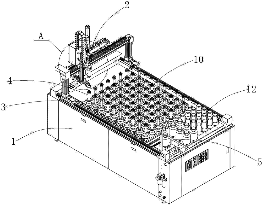
[0027] Such as figure 1 with figure 2 As shown, the present invention provides a printing and dyeing dripping machine, which includes a machine table 1 with a liquid taking area 10 for placing mother liquor bottles and a liquid dispensing area 12 for placing dye cups. A three-axis manipulator 2 is arranged above the liquid area, and the manipulator cooperates with the syringe to transfer the mother liquid into the dye cup on the liquid preparation area and insert the syringe back into the corresponding mother liquid bottle. reference figure 1 , There are multiple mother liquid bottles 3 in multiple rows and multiple columns in the liquid taking area 10, and each mother liquid bottle 3 is equipped with a syringe 4, so there is no need to clean the liquid when dispensing, and the dripping speed is very fast. The robot automatically according to the control center The instructions need to move the syringe automatically; the liquid dispensing operation is also instructed by the con...

Embodiment 2

[0034] reference Figure 4 with Figure 5 The structure of the dripping machine in this embodiment and the printing and dyeing dripping machine described in Embodiment 1 are roughly the same. The difference is that the robot 2 is also provided with a drip pan 7 under the syringe 4 that is clamped. There is a liquid receiving groove 70 on the top surface of the liquid receiving pan, and the liquid receiving pan is fixed to the manipulator by a telescopic mechanism 8 which can move synchronously with the manipulator and can make a telescopic movement in the horizontal direction. reference Figure 4 The telescopic mechanism includes a track 80, a slider 82 located on the track, and an air cylinder 84. The wetted pan 7 is fixed to the slider by a wetted pan fixing member 86, so that the air cylinder can control the horizontal telescopic movement of the wetted pan .

[0035] When the manipulator grips the syringe from the mother liquid bottle, the drip tray is retracted to provide sp...


PUM


Abstract

The invention relates to a printing and dyeing drip machine which comprises a machine body. A liquid taking area used for placing mother liquid bottles and a liquid blending area used for placing dyeing cups are arranged on the machine body, a triaxial manipulator is arranged above the liquid taking area, the triaxial manipulator and injectors are cooperatively used to deliver mother liquid to the dyeing cups in the liquid blending area, and the injectors are inserted into the corresponding mother liquid bottles; a liquid soaking area and a water charging system are further arranged on the machine body, the liquid soaking area includes a weighing area and a stirring area, a weighing unit is arranged in the weighing area, a plurality of positioning holes used for placing the mother liquid bottles are arranged in the stirring area, one magnetic stirrer is arranged correspondingly under each positioning hole, the water charging system is provided with a water outlet pipe, the water outlet of the water outlet pipe is arranged correspondingly to the weighing unit in the weighing area. By the arrangement, the problem that an existing drip machine does not have liquid soaking and stirring functions is solved.

Description

Technical field [0001] The invention relates to the textile dyeing and finishing industry, in particular to this printing and dyeing dripping machine applied to the automatic preparation of laboratory dyes. Background technique [0002] As a more advanced automatic dye color matching system, the pipeless drip system is widely used in the production and scientific research fields related to dye color matching, such as printing and dyeing enterprises, university laboratories and laboratories. With the improvement of the technical level, the pipeless dripping system has completely replaced the traditional manual liquid suction operation method. The color matching operation process is completely controlled by the computer, which not only reduces the labor intensity of the workers, but also improves the liquid preparation. Precision and efficiency. [0003] The existing pipeless automatic dripping machine has only a liquid-taking area for mother liquor, a liquid-dispensing area for a d...

Claims


Application Information

Patent Timeline
IPC IPC(8): D06B1/08D06B23/00D06B23/22D06B23/20
CPCD06B1/08D06B23/00D06B23/20D06B23/22D06B2700/36D06B23/205
Inventor 汤瑞能
Owner 厦门瑞比精密机械有限公司
Why Eureka
Try Eureka