
Laser mirror calibration system and laser mirror calibration method

A laser vibrating mirror and correction system technology, which is applied in the direction of determining the optical axis, determining the position of the lens, testing optical performance, etc., can solve the problem of low precision, and achieve the effect of improving the accuracy of correction and improving the accuracy

Inactive Publication Date: 2017-11-21
ZHENJIANG JINHAICHUANG TECH
View PDF2 Cites 15 Cited by
  • Summary
  • Abstract
  • Description
  • Claims
  • Application Information

AI Technical Summary

Problems solved by technology

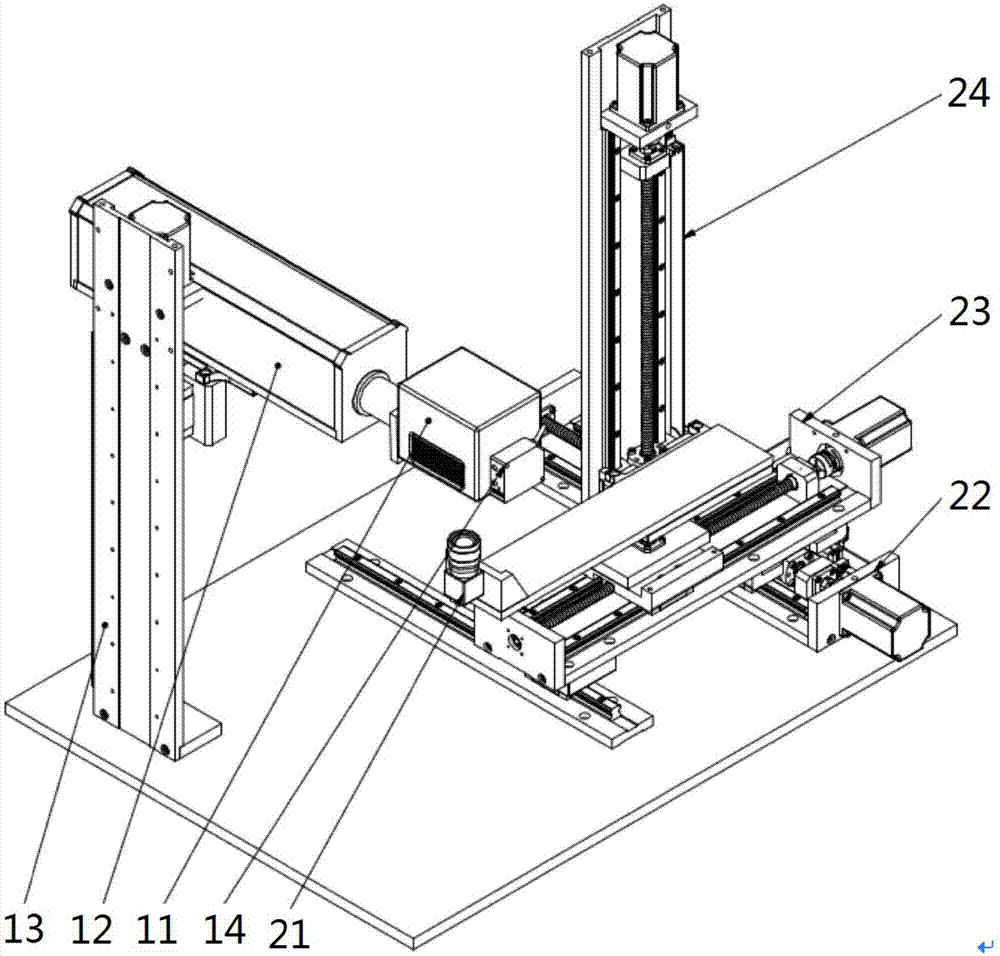
[0007] The purpose of the present invention is to provide a laser galvanometer correction system and a laser galvanometer correction method to solve the technical problem of low accuracy in data acquisition in the laser galvanometer correction process existing in the prior art

Method used


Image

  • Laser mirror calibration system and laser mirror calibration method
  • Laser mirror calibration system and laser mirror calibration method
  • Laser mirror calibration system and laser mirror calibration method

Examples


Embodiment Construction

[0044] The technical solutions of the present invention will be clearly and completely described below in conjunction with the accompanying drawings. Apparently, the described embodiments are some of the embodiments of the present invention, but not all of them. Based on the embodiments of the present invention, all other embodiments obtained by persons of ordinary skill in the art without making creative efforts belong to the protection scope of the present invention.

[0045] In the description of the present invention, it should be noted that the terms "center", "upper", "lower", "left", "right", "vertical", "horizontal", "inner", "outer" etc. The indicated orientation or positional relationship is based on the orientation or positional relationship shown in the drawings, and is only for the convenience of describing the present invention and simplifying the description, rather than indicating or implying that the referred device or element must have a specific orientation, ...


PUM


Abstract

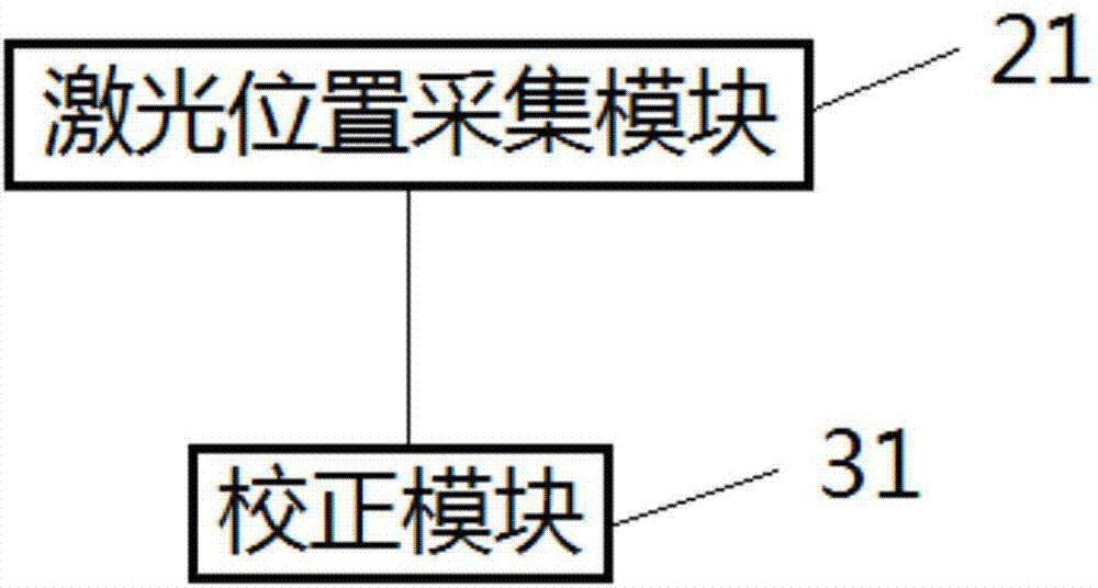
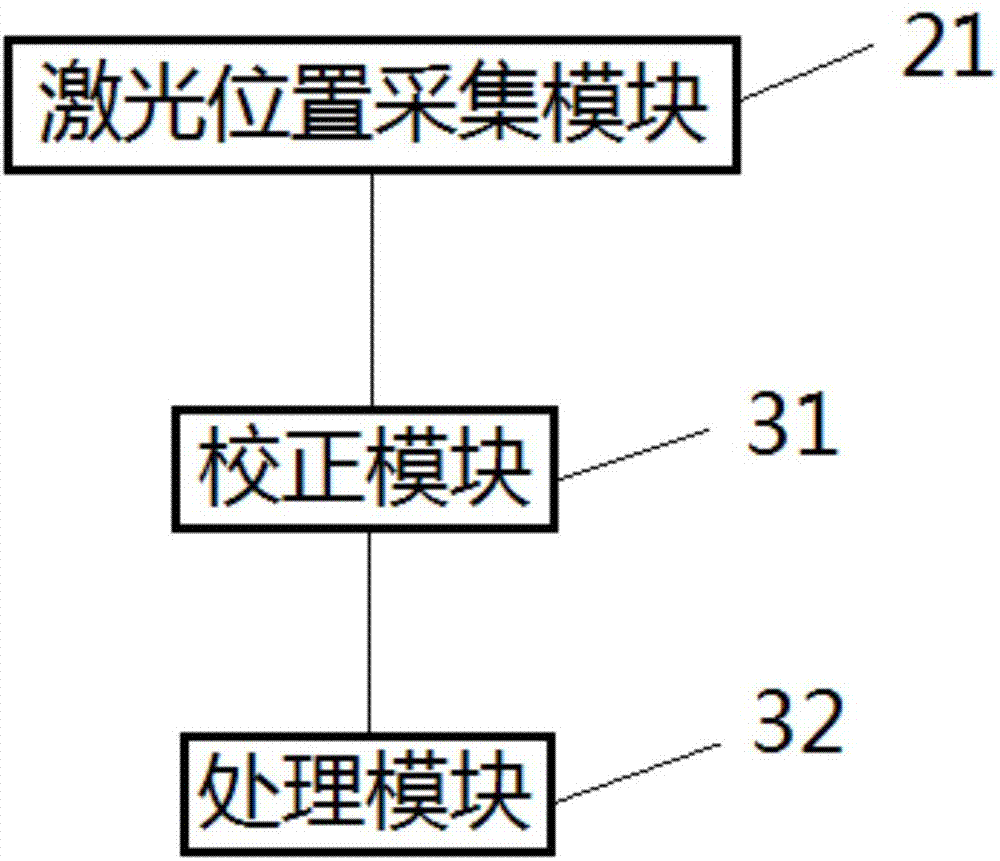
The invention provides a laser mirror calibration system and a laser mirror calibration method and relates to the technical field of laser mirrors. The laser mirror calibration system comprises a laser detection unit and a calibration unit which are electrically connected; the laser detection unit comprises a mirror control mechanism and a laser collecting mechanism; the mirror control mechanism comprises a laser support used for fixing the mirrors and lasers; the laser collecting mechanism comprises a displacement assembly and a laser location collecting module which are connected; the calibration unit comprises a calibration module which is electrically connected with the laser location collecting module and used for generating calibrated-location information according to the laser location information collected through the laser location collecting module. By the arrangement, the laser location collecting module can automatically sense laser optical pathment emitted by the lasers, location information of laser spots can be automatically detected, and location calibration can be automatically performed according to detection results.

Description

technical field [0001] The invention relates to the technical field of laser vibrating mirrors, in particular to a laser vibrating mirror correction system and a laser vibrating mirror correction method. Background technique [0002] At present, the scanning galvanometer has become the mainstream technology in the field of laser marking because of its excellent performance. With the improvement of processing density and the increase of processing width, higher requirements are put forward for the precision of the whole machine. [0003] Usually, various nonlinear errors caused by the introduction of the galvanometer system are difficult to eliminate. With the expansion of the marking area, various geometric distortions become more prominent, which seriously affects the processing accuracy of laser marking. The commonly used calibration method in the prior art is to let the galvanometer mark a matrix target, then collect the coordinates of the points on the target, and perfo...

Claims


Application Information

Patent Timeline
Patent Type & Authority Applications(China)
IPC IPC(8): G01M11/02
CPCG01M11/0221
Inventor 陈双燕
Owner ZHENJIANG JINHAICHUANG TECH
Learn More