Fluorescence detection device

A fluorescence detection and light source technology, applied in the field of optical detection, can solve problems such as difficult processing, long optical path, edge effect, etc., and achieve the effect of facilitating subsequent engineering, solving inhomogeneity, and clear process introduction

Pending Publication Date: 2017-11-21
苏州合惠生物科技有限公司
View PDF0 Cites 2 Cited by
  • Summary
  • Abstract
  • Description
  • Claims
  • Application Information

AI Technical Summary

Problems solved by technology

[0002] At present, many fluorescence detection devices on the market use a diphasic color lens to form a certain angle between the detection sample, the excitation light source and the fluorescence receiving device. This solution not only has high cost, but also has disadvantages such as weak signal (long optical path) and edge effects. , based on the above considerations, the invention of the fluorescence detection device
[0003] One of the existing fluorescent detection devices adopts the structure of the top laser, and its defect is that the signal is relatively weak. The second is the structure of using the side laser. Since the optical fibers are all drawn out from the side, it takes up a lot of space and cannot achieve large-scale detection. Simultaneous detection of quantity, and difficult processing, unable to be engineered for production

Method used


Image

  • Fluorescence detection device
  • Fluorescence detection device

Examples


Embodiment Construction

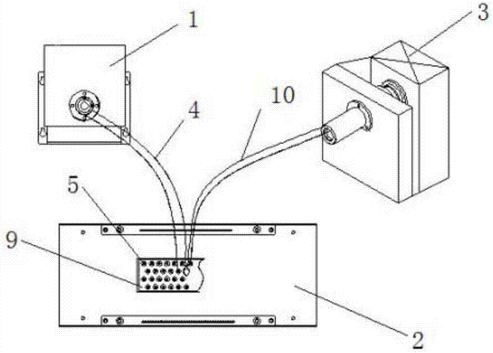
[0014] See figure 1 and figure 2 As shown, a fluorescence detection device includes a laser light source device 1, a heat sink device 2 and an incident fluorescence detection device 3, and the laser light source device 1 communicates with the bottom of the sample tube 5 on the upper surface of the heat sink device 2 through an excitation fiber 4 , the receiving optical fibers 10 are converged into a bundle and connected to the incident fluorescence detection device 3, and the incident fluorescence detection device 3 is connected to a single-chip microcomputer to read and process the signal.

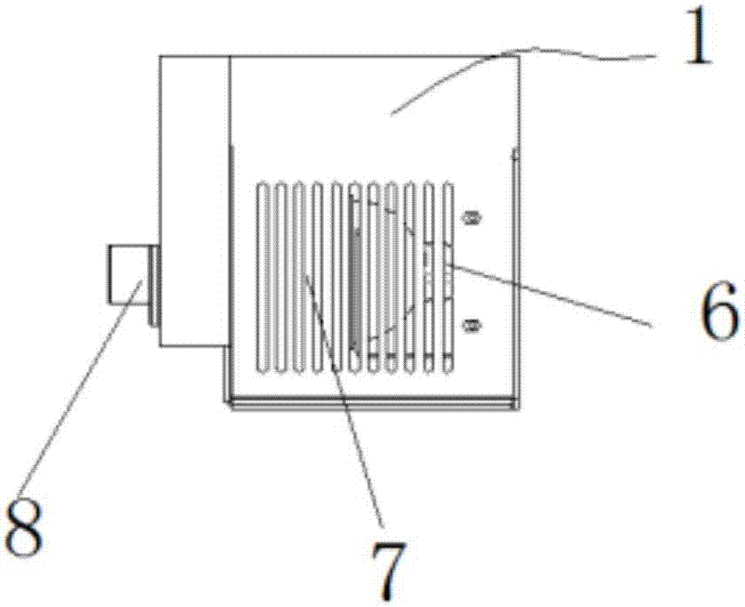
[0015] The laser light source 6 , the lens group 7 and the interference filter group 8 of the laser light source device 1 , the light emitted by the laser light source 6 enters the excitation fiber 4 through the lens group 7 and the interference filter group 8 .

[0016] The distribution number of sample tubes 5 on the upper surface of the radiator device 2 is 4*12, 4*24 or 4*48. The u...


PUM


Abstract

The invention discloses a fluorescence detection device, which comprises a laser light source device, a radiator device and an incident fluorescence detection device. The laser light source device communicates with the bottom of the sample tube on the upper surface of the radiator device through an exciting optical fiber, and the receiving optical fibers converge into a bundle. It is connected with the incident fluorescence detection device, and the incident fluorescence detection device is connected with a single-chip microcomputer to read and process the signal. The technical solution of the present invention is not only simple and practical, but also convenient for subsequent engineering, batch production, and clear process introduction; two optical fibers reach the bottom of the sample, The signal is strong, which saves the problem of weak optical signal in other solutions; and the optical path between the optical fiber and the sample can be adjusted freely to achieve free adjustment of light intensity, which solves the problem of light inhomogeneity in traditional solutions.

Description

technical field [0001] The invention relates to the technical field of optical detection, in particular to a fluorescence detection device. Background technique [0002] At present, many fluorescence detection devices on the market use a diphasic color lens to form a certain angle between the detection sample, the excitation light source and the fluorescence receiving device. This solution not only has high cost, but also has disadvantages such as weak signal (long optical path) and edge effects. , based on the above considerations, the fluorescence detection device was invented. [0003] One of the existing fluorescent detection devices adopts the structure of the top laser, and its defect is that the signal is relatively weak. The second is the structure of using the side laser. Since the optical fibers are all drawn out from the side, it takes up a lot of space and cannot achieve large-scale detection. Quantity is detected at the same time, and the processing is difficul...

Claims


Application Information

Patent Timeline
Patent Type & Authority Applications(China)
IPC IPC(8): G01N21/64G01N21/01
CPCG01N21/6402G01N21/01
Inventor 丁代明
Owner 苏州合惠生物科技有限公司
Why Eureka
Try Eureka