Liquid crystal lens structure, liquid crystal lens forming method, display panel and display device

A liquid crystal lens, display panel technology, applied in optics, instruments, nonlinear optics, etc., can solve the problems of large driving voltage and high energy consumption, and achieve the effects of large optical path difference, reduced power consumption, and large deflection

Active Publication Date: 2017-11-21
BOE TECH GRP CO LTD
View PDF4 Cites 3 Cited by
  • Summary
  • Abstract
  • Description
  • Claims
  • Application Information

AI Technical Summary

Problems solved by technology

Under the allowable driving voltage, the optical path difference can reach a maximum of 5061nm, and to reach the target value of 6500nm, a driving voltage of at least 12V is required. This driving voltage is relatively large, not suitable for small-sized liquid crystal lenses, and has high energy consumption.

Method used


Image

  • Liquid crystal lens structure, liquid crystal lens forming method, display panel and display device
  • Liquid crystal lens structure, liquid crystal lens forming method, display panel and display device
  • Liquid crystal lens structure, liquid crystal lens forming method, display panel and display device

Examples


Embodiment Construction

[0034] Embodiments of the present invention are described in detail below, examples of which are shown in the drawings, wherein the same or similar reference numerals designate the same or similar elements or elements having the same or similar functions throughout. The embodiments described below by referring to the figures are exemplary only for explaining the present invention and should not be construed as limiting the present invention. Also, detailed descriptions of known arts will be omitted if they are unnecessary to illustrate the features of the present invention.

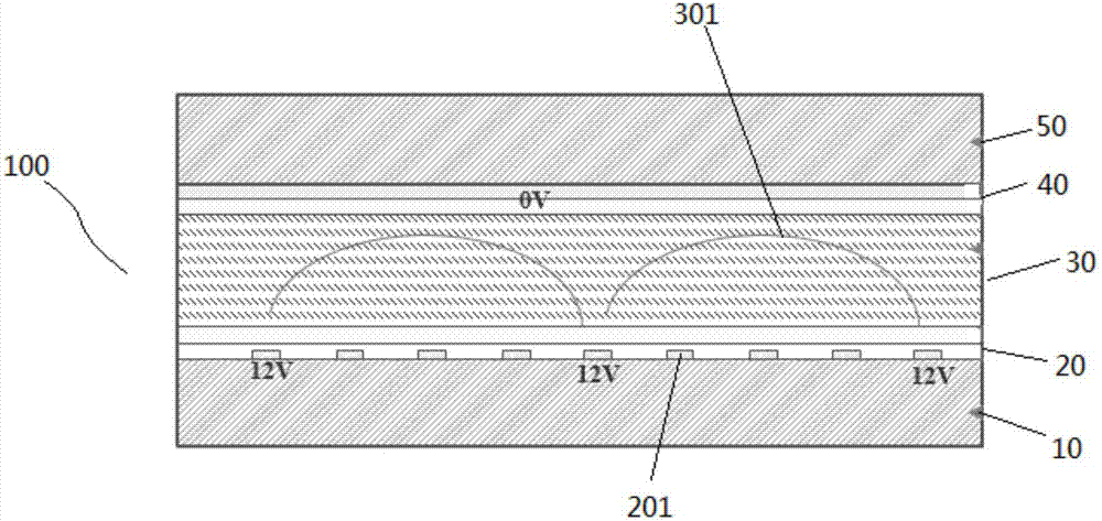
[0035] Please combine figure 2The liquid crystal lens structure 100 of the present invention includes a first substrate 10 , a first electrode layer 20 , a liquid crystal layer 30 , a second electrode layer 40 and a second substrate 50 which are sequentially stacked. Preferably, both the first electrode layer 20 and the second electrode layer 40 are made of ITO material (Indium Tin Oxide, dilutely doped...


PUM


Abstract

The invention provides a liquid crystal lens structure which comprises a first substrate, a first electrode layer, a liquid crystal layer, a second electrode layer and a second substrate which are sequentially stacked. The first electrode layer comprises a plurality of first strip electrodes, the first electrode layer and the second electrode layer are mutually matched, a lens unit can be formed in the liquid crystal layer, the first strip electrodes close to two end points of the lens unit are correspondingly matched with second strip electrodes, and voltage can be applied to the first strip electrodes and the second strip electrodes. According to the liquid crystal lens structure, light rays passing the liquid crystal lens structure can have high optical path difference, good imaging effects are achieved, and power consumption is reduced. The invention further provides a display panel, a display device and a liquid crystal lens forming method applicable to the liquid crystal lens structure.

Description

technical field [0001] The present invention relates to the field of display technology, in particular, the present invention relates to a liquid crystal lens structure, a display panel and a display device using the liquid crystal lens structure, and a method for forming a liquid crystal lens. Background technique [0002] With the continuous development of display technology, 3D display has become more and more important in the field of display. The principle of 3D display is to make people's left and right eyes receive different images, and after brain processing, the received images Create a three-dimensional effect. [0003] At present, 3D display is divided into two categories: naked-eye type and glasses-type, and liquid crystal lens is a way to realize naked-eye 3D display. Usually the liquid crystal lens is set on the display panel. The basic structure of the existing liquid crystal lens includes an upper substrate, a lower substrate and a liquid crystal layer arran...

Claims


Application Information

Patent Timeline
Patent Type & Authority Applications(China)
IPC IPC(8): G02F1/29G02F1/1343G02B27/22
CPCG02F1/134309G02F1/29G02B30/27
Inventor 王海燕
Owner BOE TECH GRP CO LTD
Why Eureka
Try Eureka