
System and method suitable for low-pressure steam-water separation

A steam-water separation, low-pressure technology, applied in separation methods, dispersed particle separation, chemical instruments and methods, etc., can solve the problems of high separator resistance, limited separation efficiency, and high steam parameters, achieve high removal efficiency, and improve vapor-liquid The effect of improving separation efficiency and flow uniformity

Active Publication Date: 2017-11-24
SHANGHAI HUIMIN ENERGY TECH
View PDF7 Cites 6 Cited by
  • Summary
  • Abstract
  • Description
  • Claims
  • Application Information

AI Technical Summary

Problems solved by technology

[0003] The invention proposes a system and method suitable for low-pressure steam-water separation in view of the defects in the prior art such as limited separation efficiency, high applied steam parameters, large separator resistance, and no low-pressure high-flow steam separator. , the primary flow equalization technology is adopted, that is, through the cylindrical flow uniform distribution structure in the inlet steam flow uniform distribution device, a large number of round holes with a diameter of about 5-10 mm are provided on the wall and bottom of the cylinder to match the separator with higher speed requirements, and adopt Secondary flow equalization technology, that is, through the flow uniform distribution cylinder structure composed of different hook types and flap spacing to match the separator with lower flow velocity requirements, to achieve the matching of flow uniform distribution and speed; finally realize the optimization of low temperature and low pressure steam Separation, through the method of system integration combined with advanced vapor-liquid separation technology, high-efficiency vapor-liquid separation can be achieved at a lower cost, and the humidity requirements of the steam entering the steam turbine can be met

Method used


Image

  • System and method suitable for low-pressure steam-water separation
  • System and method suitable for low-pressure steam-water separation
  • System and method suitable for low-pressure steam-water separation

Examples


Embodiment Construction

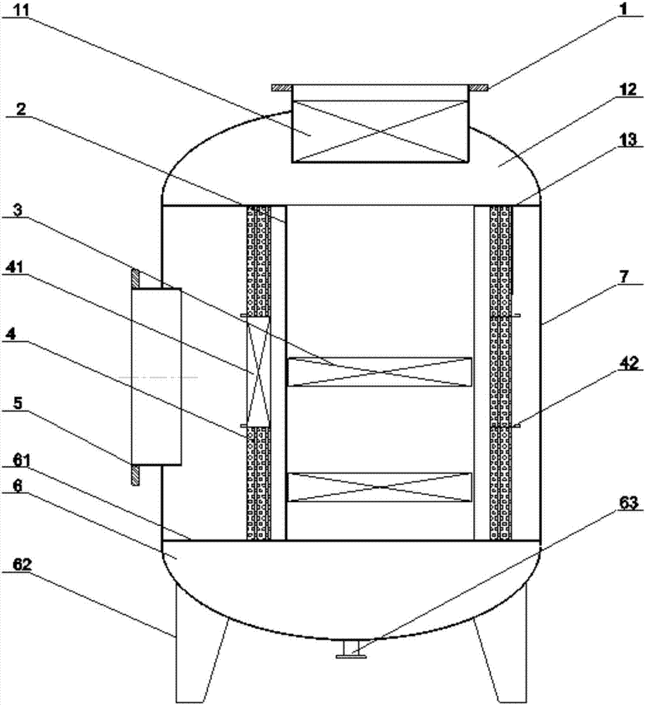
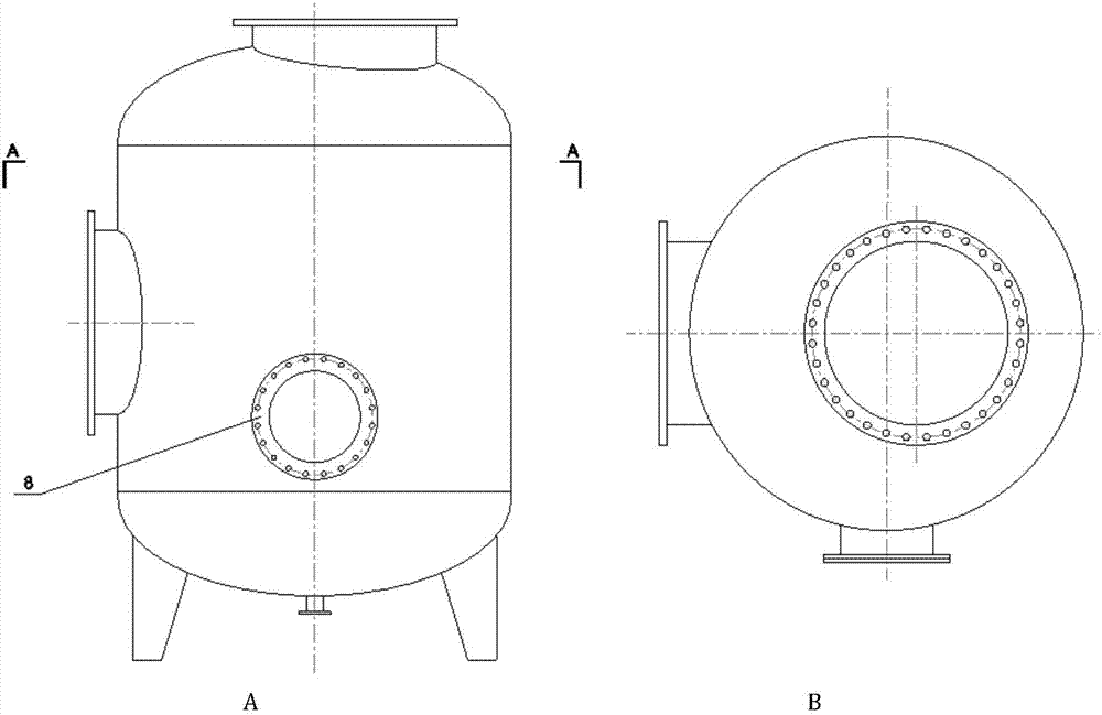
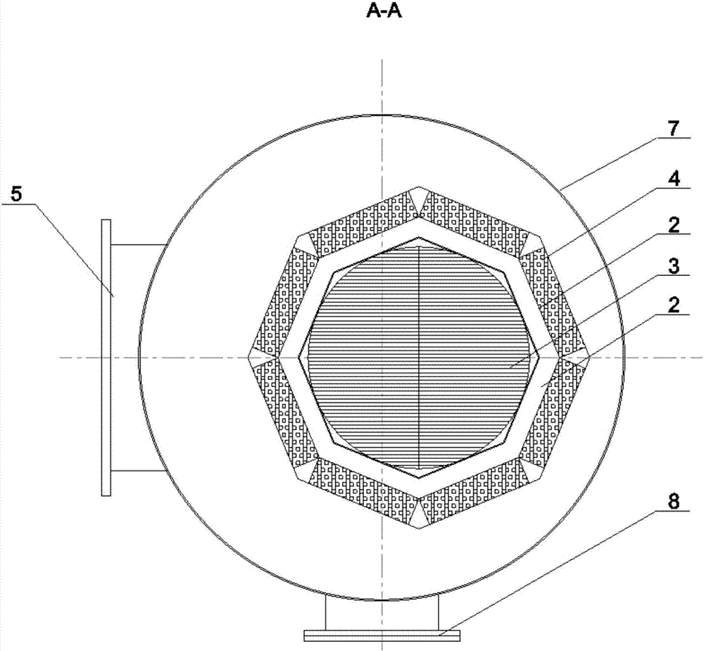
[0043] Such as figure 1 As shown, this embodiment includes: steam inlet 1, inlet steam distribution device 11, buffer steam chamber 12, steam chamber partition 13, flow uniform distribution cylinder 2, baffle separator 3, wire mesh separation system 4 , Reserved separation area 41, independent hydrophobic device 42, steam outlet 5, hydrophobic chamber 6, hydrophobic chamber partition 61, hydrophobic chamber base 62, hydrophobic outlet 63, vapor-liquid separator housing 7, manhole door 8.

[0044] The specific working process of this device is as follows:

[0045] The steam fluid with a certain humidity enters the steam-water separation device through the steam inlet 1 at a relatively high flow rate, and then enters the inlet steam flow uniform distribution device 11 for preliminary flow equalization, and enters the buffer steam chamber 12 after passing through the outlet of the flow equalization device 11, and after preliminary buffer Afterwards, the outlet of the buffer stea...


PUM


Abstract

The invention discloses a system and a method suitable for low-pressure steam-water separation. The system comprises a buffer chamber, a separation chamber and a hydrophobic chamber which are sequentially arranged in a housing from top to bottom, wherein a screen mesh separation system and a flow uniform-distribution barrel are sequentially arranged in a separator chamber; a team outlet is formed in a side surface of the housing; a non-uniform baffle plate for steam-liquid separation and flow-equalization is arranged in a barrel wall part of the flow uniform-distribution barrel; a uniform baffle plate for separation and diversion pressure-stabilization is horizontally arranged in a barrel chamber part. In the invention, a core concept of multi-stage distribution is adopted to realize optimal separation of low-pressure steam; a method integrated by the system is combined with the advanced steam-liquid separation technology to realize efficient steam-liquid separation with relatively low costs and meet requirements on humidity of steam entering a steam turbine.

Description

technical field [0001] The present invention relates to a technology in the field of industrial surplus low-pressure steam, in particular to a system and method applied to the steam-water separation process before the low-pressure steam enters a steam turbine. Background technique [0002] There are many low-temperature and low-pressure waste heat steam resources in some industrial fields, but due to its low energy grade and low availability, it leads to a large amount of emptying and waste. With the implementation of national energy conservation and emission reduction policies and the improvement of energy conservation awareness of enterprises, a process method using low-temperature and low-pressure waste heat steam for power generation is being steadily promoted, using an expander to convert thermal energy into electrical energy. In this process, organic Lang Ken cycle, or direct use of low-pressure steam Rankine cycle, due to the problems of secondary heat exchange and le...

Claims


Application Information

Patent Timeline
IPC IPC(8): B01D45/06B01D45/08
CPCB01D45/06B01D45/08
Inventor 林鹏云陆方吴文广金俊陈晶姜永浩
Owner SHANGHAI HUIMIN ENERGY TECH
Learn More