Manufacturing method and device for composite friction stirring near-net forming additional material
A friction stir, near-net-shape technology, applied in manufacturing tools, non-electric welding equipment, welding equipment, etc., can solve the problems of high clamping requirements, long processing time, complicated disassembly and assembly, etc. Material efficiency and simple device structure
- Summary
- Abstract
- Description
- Claims
- Application Information
AI Technical Summary
Problems solved by technology
Method used
Image

Examples
Embodiment 1
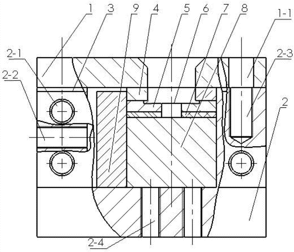
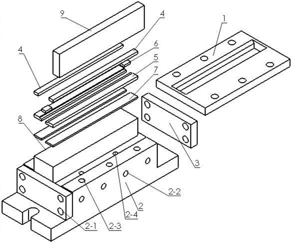
[0032] Such as Figure 1-3 As shown, this embodiment describes in detail a manufacturing method and device for friction stir near-net shape additive of composite materials according to the present invention.
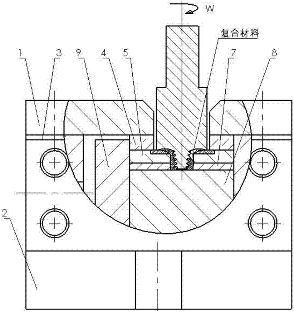
[0033] Such as figure 1 and 2 As shown, this embodiment provides a device for friction stir near-net shape additive of composite materials, including a mold base 2, a cavity plate and a cover plate 1, and end stops are installed at both ends of the mold base 2 Plate 3, a pad 8 is placed in the cavity of the mold base 2, and the two ends of the pad 8 are against the end baffle 3, and the side of the pad 8 is equipped with a side baffle 9, and the side baffle 9 and the two A terminal baffle can better stabilize the cushion block 8. A cavity plate is arranged on the top of the cushion block 8. The cavity plate is arranged as a left and right split and a rectangular gap is reserved in the middle. The cover plate 1 is connected to the upper part of the mold base 2. There i...
Embodiment 2
[0045] Embodiment 2, in step 2, the width of the plug 6 is 9mm ± 0.01, the material thickness is 4mm, the rotation speed is 600rpm, the welding speed is 45mm / min, the inclination angle of the stirring head is 2°, and the stirring needle is stirred at least 5 times; other steps and embodiments same.
Embodiment 3
[0046] Embodiment 3, in step 2, the width of the plug 6 is 10.5±0.01mm, the material thickness is 4mm, the rotation speed is 750rpm, the welding speed is 30mm / min, the inclination angle of the stirring head is 2°, and the stirring needle is stirred at least 5 times; other steps and implementation Example is the same.
PUM
| Property | Measurement | Unit |
|---|---|---|
| Width | aaaaa | aaaaa |
| Thickness | aaaaa | aaaaa |
Abstract
Description
Claims
Application Information
PatSnap Eureka turns technology decisions into work you can execute. Powered by our Innovation Knowledge Graph, it runs expert workflows across engineering, life sciences, materials and intellectual property. Get your review-ready output in minutes.


