Three-dimensional compensation device for laser welding of complicated joint seam space

A laser welding and compensation device technology, which is applied in laser welding equipment, welding equipment, metal processing equipment, etc., can solve the problems that the welding device cannot control the posture of the welding torch, and it is difficult to meet the compensation control requirements of complex seam welding, so as to achieve high efficiency and high efficiency. Quality welding, high production efficiency, and good welding quality

Pending Publication Date: 2017-11-24
HUAZHONG UNIV OF SCI & TECH
View PDF5 Cites 6 Cited by
  • Summary
  • Abstract
  • Description
  • Claims
  • Application Information

AI Technical Summary

Problems solved by technology

[0004] Aiming at the above defects or improvement needs of the prior art, the present invention provides a three-dimensional compensation device for laser welding complex seam space, in which combined with the characteristics of laser complex seam welding itself, a device suitable for laser welding complex seam space is designed accordingly. Three-dimensional compensation device, and the specific structure and specific layout of its key components such as fixed mechanism, rotating mechanism and linear motion mechanism are researched and designed. Correspondingly, it can effectively solve the problem that the existing welding device cannot control the attitude of the welding torch and is difficult to meet the complex welding requirements. Seam welding compensation control requirements, but also has the characteristics of compact and reasonable structure, light weight, high control precision, rapid movement response, etc., so it has universal applicability

Method used


Image

  • Three-dimensional compensation device for laser welding of complicated joint seam space
  • Three-dimensional compensation device for laser welding of complicated joint seam space
  • Three-dimensional compensation device for laser welding of complicated joint seam space

Examples


Embodiment Construction

[0023] In order to make the object, technical solution and advantages of the present invention clearer, the present invention will be further described in detail below in conjunction with the accompanying drawings and embodiments. It should be understood that the specific embodiments described here are only used to explain the present invention, not to limit the present invention. In addition, the technical features involved in the various embodiments of the present invention described below can be combined with each other as long as they do not constitute a conflict with each other.

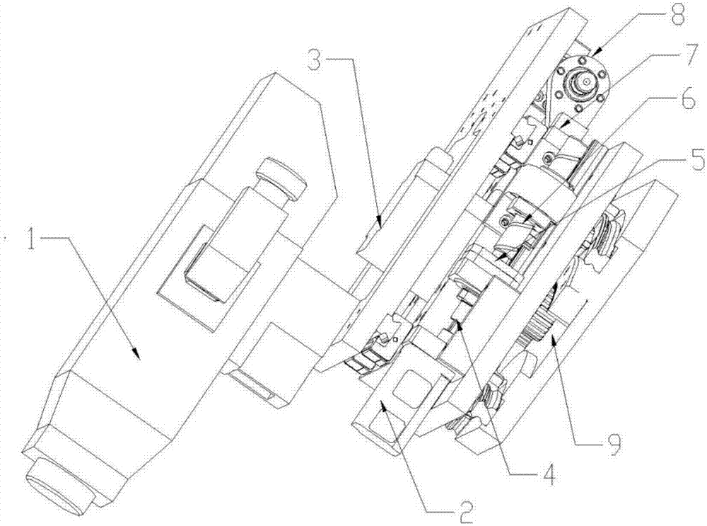
[0024] Such as figure 1 As shown, the embodiment of the present invention provides a three-dimensional compensation device for laser welding complex seam space, which includes a fixing mechanism, a rotating mechanism 9 and a linear motion mechanism, wherein the fixing mechanism is used to fix and install the rotating mechanism 9 and the linear motion mechanism, The rotating mechanism is used fo...


PUM


Abstract

The invention belongs to the technical field of laser welding equipment and particularly discloses a three-dimensional compensation device for laser welding of a complicated joint seam space. The three-dimensional compensation device comprises a fixing mechanism, a rotating mechanism and a linear movement mechanism. The fixing mechanism comprises a first fixing plate, a second fixing plate, a third fixing plate and a fourth fixing plate. A rotary guide rail and a rack are arranged on the first fixing plate. A rotary sliding block and a vertical movement guide rail are arranged on the second fixing plate. A vertical movement sliding block and a horizontal movement sliding block are arranged on the third fixing plate. A horizontal movement guide rail and a welding gun are arranged on the fourth fixing plate. The rotating mechanism comprises a rotary servo motor and a gear connected with the rotary servo motor. The rotary servo motor is mounted on the second fixing plate. The gear is engaged with the rack. The linear movement mechanism comprises a vertical movement mechanism and a horizontal movement mechanism. The vertical movement mechanism is arranged on the second fixing plate. The horizontal movement mechanism is arranged on the third fixing plate. The three-dimensional compensation device has the beneficial effects of being flexible to move, high in control accuracy, high in production efficiency, good in welding quality and the like.

Description

technical field [0001] The invention belongs to the technical field of laser welding equipment, and more specifically relates to a three-dimensional compensation device for laser welding complex seam space. Background technique [0002] At present, teaching robots are widely used for laser welding in China. In ordinary flat seam welding, the path teaching of this method is simple, the assembly error is small, and high-efficiency and high-quality laser welding can be achieved. However, the welding path of complex patchwork is often a three-dimensional space curve, and its shape is irregular. Therefore, it is difficult to teach the path of complex patchwork robot welding, coupled with the difficulty of assembly, the welding efficiency is often low, and the equipment error of complex patchwork welding is large, and the welding quality is low. [0003] Laser welding online compensation technology can control the actual welding torch position during the welding process, so as to...

Claims


Application Information

Patent Timeline
IPC IPC(8): B23K26/21B23K26/08B23K26/70
CPCB23K26/08B23K26/21B23K26/702
Inventor 黄禹荣佑民龚时华徐加俊赵业强蒋平郑豪杰雷艇
Owner HUAZHONG UNIV OF SCI & TECH
Why Eureka
Try Eureka