Eureka AIR delivers breakthrough ideas for toughest innovation challenges, trusted by R&D personnel around the world.

Environmentally-friendly sludge treatment device

A sludge treatment, environmentally friendly technology, applied in sludge treatment, water/sludge/sewage treatment, sludge treatment through temperature control, etc. problem, to achieve the effect of good sludge treatment, simple structure and strong practicability

Inactive Publication Date: 2017-11-24
ZHENGZHOU TIANSHUN ELECTRONICS TECH CO LTD
View PDF5 Cites 7 Cited by
  • Summary
  • Abstract
  • Description
  • Claims
  • Application Information

AI Technical Summary

Problems solved by technology

[0002] With the continuous improvement of my country's urbanization level, the construction of sewage treatment facilities has developed rapidly. The use of advanced sludge treatment equipment plays a very important role in sludge treatment. In order to achieve the national emission reduction goals and improve the water environment, we have made great efforts Great contribution, but the situation of sludge treatment is still very serious at present; in sludge treatment equipment, sludge dryer is a common treatment equipment, and sludge lumps are crushed and broken up in the sludge dryer, which is usually broken and broken up by the inside After the device is completed, the sludge can be dispersed and crushed to provide convenience for the subsequent drying treatment, increase the drying heating area and reduce stirring, but the traditional sludge crusher can only roughly break up the sludge, and it is very difficult It is difficult to complete the dispersal of the sludge in a detailed and sufficient manner, which brings inconvenience to the subsequent processing procedures; at the same time, the sludge is easy to produce polluting gases when it is dried, which is directly discharged to pollute the atmosphere and is harmful to humans; therefore, it needs to be improved

Method used


Image

  • Environmentally-friendly sludge treatment device
  • Environmentally-friendly sludge treatment device
  • Environmentally-friendly sludge treatment device

Examples


Embodiment Construction

[0015] The technical solution of this patent will be further described in detail below in conjunction with specific embodiments.

[0016] Embodiments of the present patent are described in detail below, examples of which are shown in the drawings, wherein the same or similar reference numerals designate the same or similar elements or elements having the same or similar functions throughout. The embodiments described below by referring to the figures are exemplary and are only used for explaining the patent, and should not be construed as limiting the patent.

[0017] In the description of this patent, it is to be understood that the terms "center", "upper", "lower", "front", "rear", "left", "right", "vertical", "horizontal", The orientation or positional relationship indicated by "top", "bottom", "inner", "outer", etc. is based on the orientation or positional relationship shown in the drawings, and is only for the convenience of describing this patent and simplifying the des...


PUM


Abstract

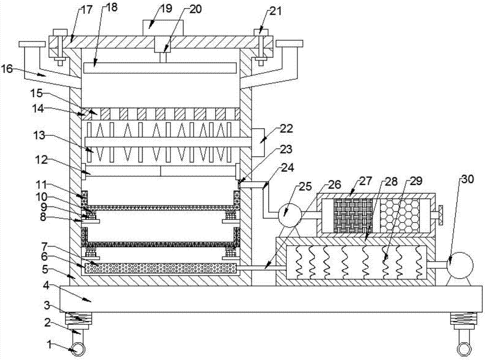
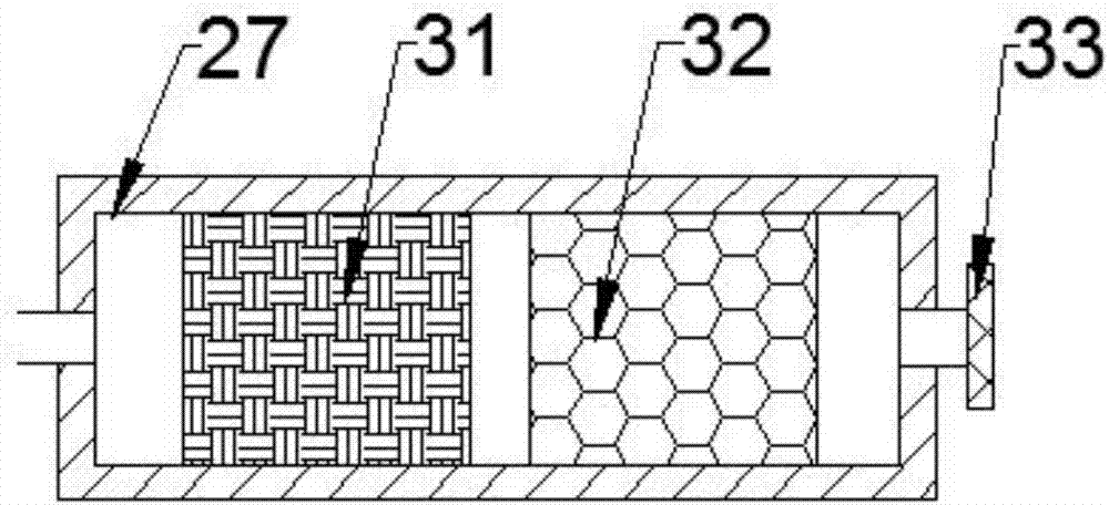
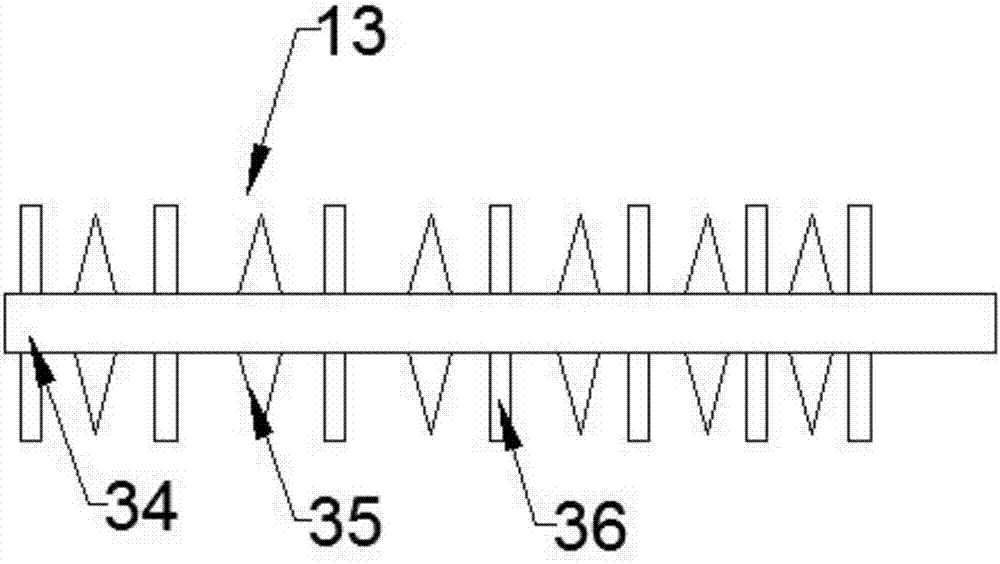
The invention provides an environmentally-friendly sludge treatment device, and belongs to the field of environmental protection and purification. A pressure plate is fixedly arranged at the lower end of a telescopic rod; a sludge pressing die is arranged at the upper side of the inner cavity of a box body; the left end of a rotating motor is fixedly welded with a crusher; a vibrator is fixedly arranged on every supporting plate, and a storage mesh vessel is arranged on the vibrators through springs; the left end of a blower is connected with a heating box through an air outlet tube; a waste gas purifying box is arranged on the heating box; and an active carbon adsorption layer is arranged at the right side of a biological reaction layer. The left end of the motor is fixedly welded with the crusher, so the device can scatter and crush extruded bar-shaped sludge blocks; the right end of a suction fan is connected with the waste gas purifying box through a suction tube, so the device can react and degrade waste gas and adsorb and purify stink; and the device has the advantages of simple structure, high practicability and good sludge treatment effect.

Description

technical field [0001] The invention relates to an environment-friendly purification related facility, in particular to an environment-friendly sludge treatment device. Background technique [0002] With the continuous improvement of my country's urbanization level, the construction of sewage treatment facilities has developed rapidly. The use of advanced sludge treatment equipment plays a very important role in sludge treatment. In order to achieve the national emission reduction goals and improve the water environment, we have made great efforts Great contribution, but the situation of sludge treatment is still very serious at present; in sludge treatment equipment, sludge dryer is a common treatment equipment, and sludge lumps are crushed and broken up in the sludge dryer, which is usually broken and broken up by the inside After the device is completed, the sludge can be dispersed and crushed to provide convenience for the subsequent drying treatment, increase the drying h...

Claims


Application Information

Patent Timeline
Patent Type & Authority Applications(China)
IPC IPC(8): C02F11/00C02F11/18B01D53/84
CPCB01D53/04B01D53/84C02F11/00C02F11/18Y02A50/20
Inventor 李欣
Owner ZHENGZHOU TIANSHUN ELECTRONICS TECH CO LTD
Why Eureka
Eureka Blog
Learn More