Automatic sewing equipment and framework thereof

A technology for sewing machines and racks, which is applied to sewing machine components, sewing equipment, textiles, and papermaking. It can solve the problems of increasing the overall occupied space of automatic sewing equipment, reducing the space utilization rate of garment factories, and the length of automatic sewing equipment. Effect of space utilization, reduction in volume and occupied space, and reduction in length

Active Publication Date: 2017-11-24
JACK SEWING MASCH CO LTD
View PDF4 Cites 6 Cited by
  • Summary
  • Abstract
  • Description
  • Claims
  • Application Information

AI Technical Summary

Problems solved by technology

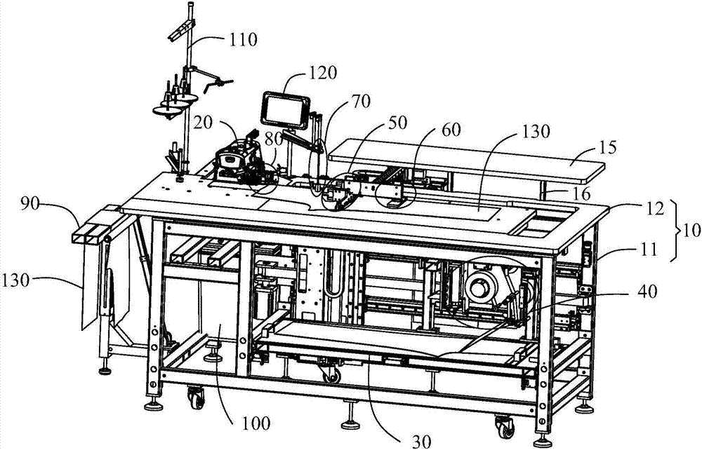
However, the automatic sewing equipment of the above structure has the following defects: since the cloth placing table is arranged on one side of the platen along the length direction of the platen, the length of the entire automatic sewing equipment is relatively long, which greatly increases the speed of the automatic sewing equipment. The overall occupied space reduces the space utilization rate of the garment factory

Method used


Image

  • Automatic sewing equipment and framework thereof
  • Automatic sewing equipment and framework thereof
  • Automatic sewing equipment and framework thereof

Examples


Embodiment 1

[0219] Embodiment one, as Figure 22 or Figure 23 As shown, the second sewing material detection sensor 14 is installed at the channel opening 124 and is fixed on the lower end side of the table 12 . At this time, the second seam detection sensor 14 can be a through-beam photoelectric sensor, which has a transmitting part 141 and a receiving part 142 that are independent from each other and arranged opposite to each other, such as Figure 22 As shown, the transmitting part 141 and the receiving part 142 are all fixed on the mounting bracket 151, and the two mounting brackets 151 are respectively installed at the left edge and the right edge of the channel opening 124, and are fixed on the lower end surface of the platen 12, and then the The second seam detection sensor 14 is installed at the channel opening 124 . Or, the second seam detection sensor 14 can also be a reflective photoelectric sensor, such as Figure 23 As shown, the sewing material length detection unit also...

Embodiment 2

[0221] Embodiment two, such as Figure 24 As shown, the second sewing material detection sensor 14 is installed on the lower end surface of the right end of the table 12 and is adjacent to the channel opening 124, and the table 12 is provided with a second hole that penetrates up and down and allows the second sewing material detection sensor 14 to be exposed. Through hole 128; at this time, the second sewing material detection sensor 14 is a reflective photoelectric sensor. Since the second sewing material detection sensor 14 is installed on the lower end surface of the right end of the table 12, after the sewing material clamping unit 50 transfers the sewing material 130 to the designated position on the table 12, the sewing material 130 must be turned to the left. Overriding the second sewing material detection sensor 14, the table 12 must be able to accommodate a whole piece of sewing material 130, thereby relatively increasing the length of the table 12 and the overall le...


PUM


Abstract

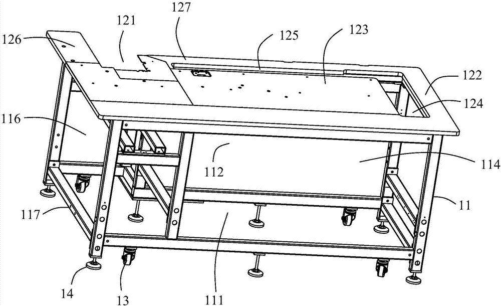
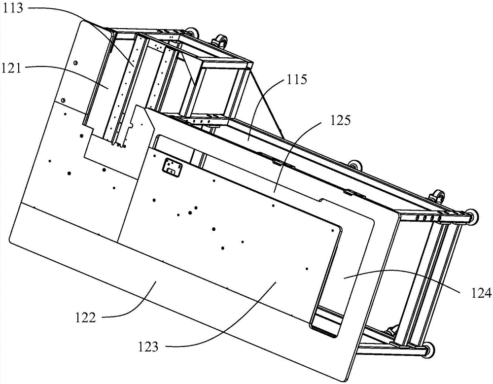
The invention provides a framework of automatic sewing equipment. The framework comprises a frame and a bedplate. The bedplate is fixed to the upper end of the frame, a discharge unit mounting location, a sewing material clamping unit mounting location and a sewing machine mounting location are arranged on the frame, a sewing machine mounting opening which is opposite to the sewing machine mounting location in the up-down directions is formed in the bedplate, the discharge unit mounting location is positioned on the lower side of the bedplate, the sewing material clamping unit mounting location and the sewing machine mounting location are arranged on the same side of the framework along the width direction of the framework, a channel opening which is perforated in the up-down directions is formed in the end, which is far away from the sewing machine mounting opening, of the bedplate, and a sewing material clamping unit in the automatic sewing equipment is allowed to pass the channel opening. The framework has the advantages that space location relations among the discharge unit mounting location, the sewing material clamping unit mounting location and the sewing machine mounting location are reasonably arranged, accordingly, the length of the framework can be reduced to a great extent, the volume and occupied spaces of the framework can be diminished, the automatic sewing equipment is quite compact in integral structure, and the utilization rate of spaces of a garment factory can be effectively increased.

Description

technical field [0001] The invention relates to a frame of automatic sewing equipment. [0002] The present invention also relates to an automatic sewing machine comprising the above machine frame. Background technique [0003] At present, automatic sewing equipment is equipped with a frame, a cloth placing table, a sewing machine and a material transfer unit. The frame is composed of a frame body and a table. The sewing machine is installed on the table, and the cloth placing table is along the length direction of the table. It is arranged on one side of the table, and the cloth placing table is flush with the table. The material moving unit moves back and forth between the table and the cloth placing table along the length direction of the table, and pulls the sewing material on the cloth placing table to platen. However, the automatic sewing equipment of the above structure has the following defects: since the cloth placing table is arranged on one side of the platen al...

Claims


Application Information

Patent Timeline
Patent Type & Authority Applications(China)
IPC IPC(8): D05B75/00
Inventor 刘顺财陈伟强李丽
Owner JACK SEWING MASCH CO LTD
Why Eureka
Try Eureka