
Uplift pile with upper straight rod and lower screw suitable for seasonal frozen soil regions and construction method thereof

A technology for uplift piles and permafrost areas, applied in sheet pile walls, foundation structure engineering, protection devices, etc., can solve problems such as uneconomical, reduced shear strength, and reduced bearing capacity of uplift piles, so as to ensure construction quality , The effect of improving the pull-out bearing capacity and reducing the difficulty of construction

Active Publication Date: 2017-11-24
CHONGQING JIAOTONG UNIVERSITY
View PDF5 Cites 10 Cited by
  • Summary
  • Abstract
  • Description
  • Claims
  • Application Information

AI Technical Summary

Problems solved by technology

[0004] Second, when the foundation soil around the pile thaws and settles, because the solid ice in the soil gradually transforms into liquid water during the thawing process, the shear strength of the soil will decrease significantly, and may even be lower than the value before frost heave, making The shear strength of the pile-soil interface decreases, the bearing capacity of the uplift pile decreases, and the displacement of the pile top increases under the same load; The reduction of the shear strength of the soil interface also develops gradually from the surface down.
[0006] Although the first type of method can eliminate or partially eliminate the influence of frost heave-thaw settlement on the bearing characteristics of uplift piles, it is obviously uneconomical; the second type of method can improve the safety of uplift piles and properly reduce frost heave-thaw However, it cannot eliminate the influence of frost heave-thaw settlement on the load-bearing characteristics of the uplift piles, which is naturally uneconomical

Method used


Image

  • Uplift pile with upper straight rod and lower screw suitable for seasonal frozen soil regions and construction method thereof
  • Uplift pile with upper straight rod and lower screw suitable for seasonal frozen soil regions and construction method thereof
  • Uplift pile with upper straight rod and lower screw suitable for seasonal frozen soil regions and construction method thereof

Examples


Embodiment 1

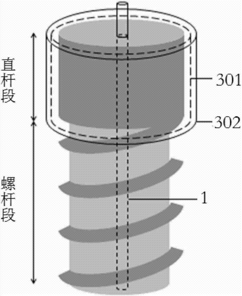
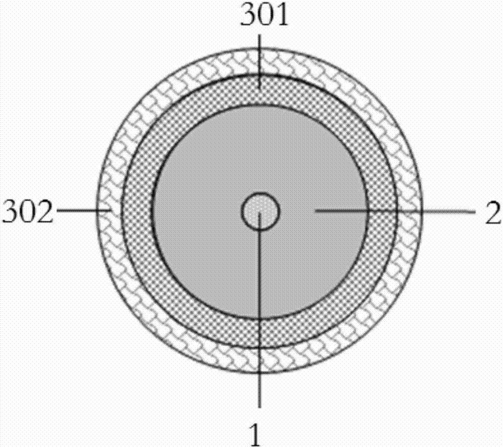
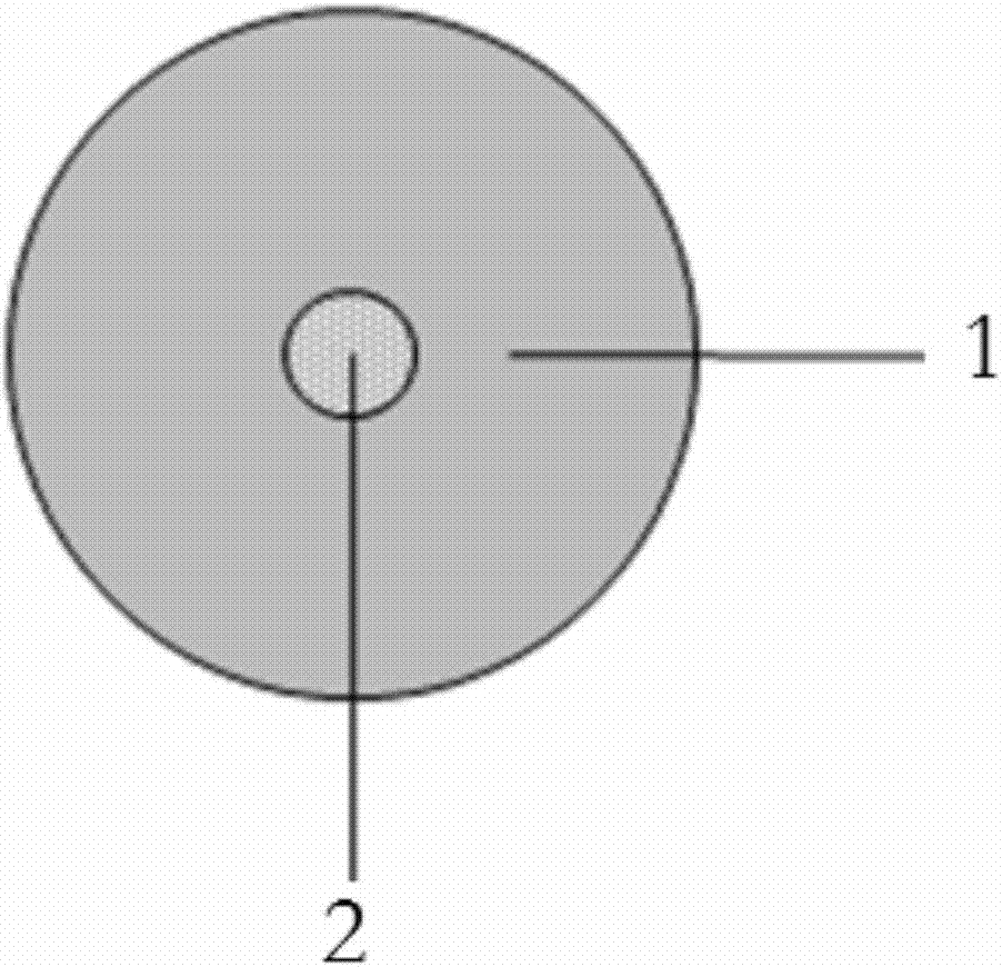
[0069] like figure 1 , figure 2 and image 3 As shown, an uplift pile with upper straight rod and lower screw rod suitable for seasonal frozen soil regions is characterized in that it includes: uplift steel bar 1 , mortar 2 and casing 3 .

[0070] The uplift pile includes a connected straight rod part and a screw part, the straight rod part is located above the uplift pile, and the screw part is located under the uplift pile.

[0071] The uplift-resistant steel bar 1 is located at the center of the uplift-resistant pile, and the uplift-resistant steel bar 1 is wrapped by mortar 2 to form a columnar structure. The pullout-resistant steel bars 1 can be replaced by steel strands.

[0072] The number of said pullout steel bars 1 is one.

[0073] The pullout steel bar 1 is provided with a ring support every 2-3m along the length direction.

[0074] A joint 101 beyond the top of the uplift pile is left on the top of the uplift steel bar 1, and the joint 101 is connected with t...

Embodiment 2

[0082] like Figure 4 , Figure 5 and Image 6 As shown, an uplift pile with upper straight rod and lower screw rod suitable for seasonal frozen soil regions is characterized in that it includes: a steel cage 1 , concrete 2 and casing 3 .

[0083] The uplift pile includes a connected straight rod part and a screw part, the straight rod part is located above the uplift pile, and the screw part is located under the uplift pile.

[0084] The reinforcement cage 1 is arranged along the axial length of the uplift pile, and the inside and outside of the reinforcement cage 1 are wrapped with concrete 2 to form a columnar structure.

[0085] All the longitudinal pull-out steel bars of the reinforcement cage 1 are equal in length.

[0086] A joint 101 beyond the top of the uplift pile is left on the top of the reinforcement cage 1, and the joint 101 is connected with the cap or the superstructure.

[0087] Threads are provided on the lower outer wall of the cylindrical structure to ...

Embodiment 3

[0094] like Figure 7 Shown, a kind of construction method of the upper straight rod lower screw rod uplift pile that is suitable for seasonal permafrost region is characterized in that, comprises the following steps:

[0095] 1) The drilling rig is in place, and the pull-out steel bars or steel cages are made.

[0096] The drill bits of the drilling rig are common straight rod drill bits and threaded rod drill bits, and the drill bits of the drilling rig can be extended as required.

[0097] 2) The straight section of the uplift pile is drilled into the hole.

[0098] The depth drilled into the ground by the straight rod drill bit is the length of the straight rod section of the uplift pile. The straight drill bit can be extended at the upper end as required.

[0099] 3) Lift the straight drill bit.

[0100] The straight-stem drill bit that has been drilled to a predetermined depth in the ground is lifted to the surface and removed.

[0101] 4) Install double-layer casin...


PUM

PropertyMeasurementUnit
Lengthaaaaaaaaaa

Abstract

The invention discloses an uplift pile with an upper straight rod and a lower screw suitable for seasonal frozen soil regions and a construction method thereof. The uplift pile is characterized by comprising a plurality of anti-punching shear bars, a sand pulp and a sleeve pipe, wherein the anti-punching shear bars are positioned at the central position of the uplift pile; the anti-punching shear bars are wrapped with the sand pulp to form a cylindrical structure; a connector protruding out of the top of each of the uplift pile is reserved at the top of each of the anti-punching shear bars; a thread is arranged on the outer wall of the lower part of the cylindrical structure to form the screw part of the uplift pile; no thread is formed on the outer wall at the upper part of the cylindrical structure so as to form the straight rod part of the uplift pile; the outer wall of the straight rod part of the uplift pile is sleeved with the sleeve pipe; the sleeve pipe comprises an inner layer sleeve pipe and an outer layer sleeve pipe; the outer layer sleeve pipe can produce displacement relative to the inner layer sleeve pipe in the axial direction of the uplift pile; the inner wall of the inner layer sleeve pipe is in contact with the sand pulp; and the outer wall of the outer layer sleeve pipe is in contact with the frost-heaving and thawing-settlement foundation.

Description

technical field [0001] The invention relates to an uplift pile, in particular to an uplift pile with an upper straight rod and a lower screw rod suitable for seasonal frozen soil regions and a construction method thereof. Background technique [0002] An uplift pile is a type of pile foundation that bears an uplift load. Its bearing capacity refers to the maximum uplift load it can bear, and deformation refers to the upward displacement of the pile top under the uplift load. In seasonally frozen soil areas, the foundation soil around the piles of the uplift piles may undergo frost heave-thaw settlement cycles due to seasonal changes. This effect will inevitably affect the bearing characteristics of the uplift piles, which are mainly reflected in two aspects: [0003] One is that when the foundation soil around the pile is frost heaved, there will be a new pile side friction force due to the relative displacement between the foundation soil and the uplift pile during the fros...

Claims


Application Information

Patent Timeline
IPC IPC(8): E02D5/56E02D5/60E02D31/14
Inventor 王俊杰付泓锐赵迪杨洋汪魁阿比尔的
Owner CHONGQING JIAOTONG UNIVERSITY
Learn More