
Eureka
For R&D, Eureka makes reading and utilizing patents & technical documents easy.
Eureka AIR
Designed for self-driven R&D workflows. Generate viable solutions, solve complex R&D challenges, empower your innovation with AI.

Eureka Materials
Designed for material experts only. Revolutionize your material R&D, from search, analyze, to developing new materials.

TechResearch
Generate reliable direction feasibility study reports for your R&D in just a few steps.

TechSeek
Discover and master advanced knowledge NOW. Basics, ideas, possibilities, all at once.

TechMind
As an expert in R&D Theories, TechMind can generates customized viable solutions instantly.

TechRisk
Analyze your overall solution with one click, know your potential R&D risks in advance.

TechMonitor
Get weekly tech updates, stay abreast of the latest tech innovations and key insights.
Colluvial clay tunnel pipe shed structure and colluvial clay tunnel construction method
A tunnel pipe and shed structure technology, applied in tunnels, tunnel linings, earthwork drilling and mining, etc., can solve the problems of large hidden dangers of collapse of landslide deposits, achieve strong bearing capacity, and avoid affecting construction or accidents
- Summary
- Abstract
- Description
- Claims
- Application Information
AI Technical Summary
Problems solved by technology
Method used
Image

Examples
Embodiment 1
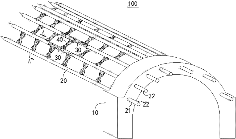
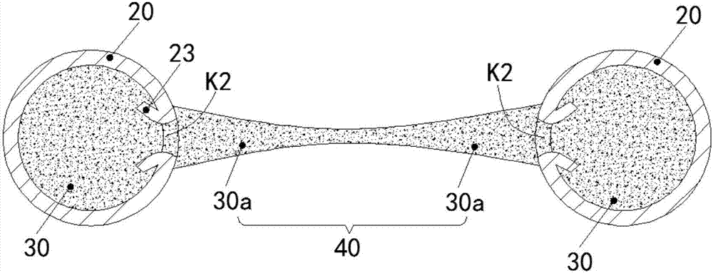
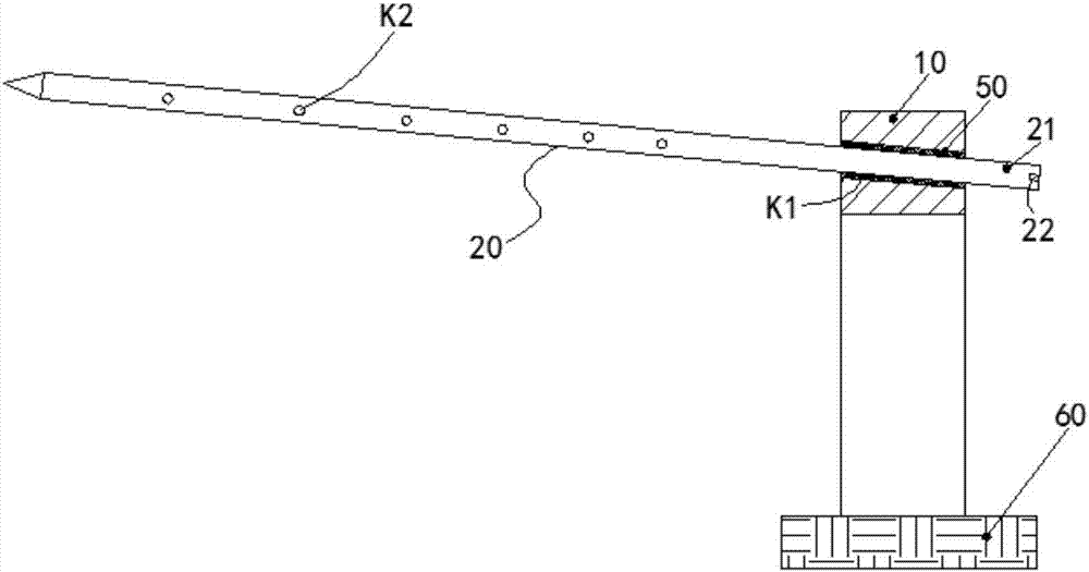
[0052] figure 1 It is a structural schematic diagram of the pipe shed structure 100 of the collapsing body tunnel in the embodiment of the present invention, figure 2 yes figure 1 Sectional view along line A-A; image 3 for figure 1 A longitudinal sectional view of the pipe-shelf structure 100 of the collapsing body tunnel along the depth direction of the tunnel; Figure 4 It is a view when the tunnel pipe shed structure 100 of the avalanche deposit in this embodiment is installed in the avalanche deposit T0. Please cooperate with reference figure 1 , figure 2 , image 3 , Figure 4 , the tunnel pipe shed structure 100 of the collapsing body in this embodiment includes the guide wall 10 , the main body 30 of the guide pipe 20 and the connecting body 40 . The guide wall 10 is an arched structure matching the section of the tunnel. The guide wall 10 has a plurality of guide holes K1. The guide tube 20 corresponds to each guide hole K1 , one end of the guide tube 20 i...
Embodiment 2
[0061] Figure 7 It is a flowchart of the construction method of the collapsing body tunnel in the second embodiment of the present invention. See Figure 7 (Cooperate with referring to other views in the first embodiment), the present embodiment provides a construction method of the landslide body tunnel, which includes the following steps, the construction step of the pipe shed structure: the entrances at the two ends of the tunnel are respectively set in the first embodiment The pipe shed structure 100 of the collapsing body tunnel;
[0062] Tunnel excavation steps: both ends of the tunnel are excavated at the same time until they are connected to each other;
[0063] Wherein, the installation step of the pipe shed structure includes pouring a guide wall 10 outside the tunnel entrance, and the guide wall 10 has a guide hole K1;
[0064] Insert the guide pipe 20 from the guide hole K1, and make the opposite grouting ports K2 of the adjacent guide pipes 20 face each other ...
PUM
 Abstract
Description
Claims
Application Information
 - R&D Engineer
- R&D Manager
- IP Professional
- Industry Leading Data Capabilities
- Powerful AI technology
- Patent DNA Extraction
Browse by: Latest US Patents, China's latest patents, Technical Efficacy Thesaurus, Application Domain, Technology Topic, Popular Technical Reports.
© 2024 PatSnap. All rights reserved.Legal|Privacy policy|Modern Slavery Act Transparency Statement|Sitemap|About US| Contact US: help@patsnap.com