Reciprocating compressor and control method thereof

A control method and compressor technology, applied in the field of compressors, can solve the problems of low power transmission efficiency, many friction pairs, and many moving parts, and achieve the effects of simple structure, less friction pairs, and fewer moving parts

Pending Publication Date: 2017-11-24
魏亮
View PDF2 Cites 2 Cited by
  • Summary
  • Abstract
  • Description
  • Claims
  • Application Information

AI Technical Summary

Problems solved by technology

[0002] At present, all reciprocating compressors require a crank-and-link mechanism to drive the piston, which result

Method used


Image

  • Reciprocating compressor and control method thereof
  • Reciprocating compressor and control method thereof
  • Reciprocating compressor and control method thereof

Examples


Example Embodiment

[0031] In order to make the objectives, technical solutions and advantages of the present invention clearer, the following further describes the present invention in detail with reference to the accompanying drawings and embodiments. It should be understood that the specific embodiments described herein are only used to explain the present invention, but not to limit the present invention.

[0032] The overall structure

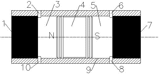
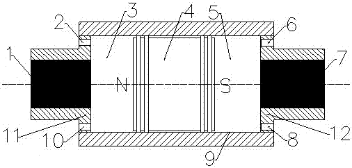
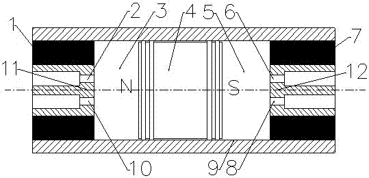
[0033] The reciprocating compressor provided by the solution of the present invention includes a cylinder (9), a permanent magnet piston (4) arranged in the cylinder (9), and a first electromagnet (1) arranged at both ends of the cylinder (9). ) And a cylinder head composed of a second electromagnet (7) or composed of a first electromagnet (1) and a first cylinder head assembly (11), a second electromagnet (7) and a second cylinder head assembly (12) Cylinder head, wherein the permanent magnet piston (4) separates the cylinder (9) between the first electromagnet...


PUM


Abstract

The invention discloses a reciprocating compressor and a control method thereof. The compressor comprises a cylinder, a permanent magnet piston arranged in the cylinder and an electromagnet arranged at two ends of the cylinder, wherein the permanent magnet piston divides the cylinder into a first compression cavity and a second compression cavity. Therefore, the compressor provided by the invention can reduce the number of moving parts and reduce the number of friction pairs.

Description

technical field [0001] The invention belongs to the technical field of compressors, and in particular relates to a reciprocating compressor and a control method thereof. Background technique [0002] At present, all reciprocating compressors require a crank-link mechanism to drive the piston, which results in more moving parts, more friction pairs and lower power transmission efficiency of the reciprocating compressor. Contents of the invention [0003] The invention provides a reciprocating compressor and a control method thereof, comprising a cylinder (9), a permanent magnet piston (4) arranged in the cylinder (9), and first pistons arranged at both ends of the cylinder (9). An electromagnet (1) and a second electromagnet (7), wherein the permanent magnet piston (4) separates the cylinder (9) into a first compression chamber (3) and a second compression chamber (5). [0004] Preferably, the central axis of the first electromagnet (1), the second electromagnet (7) and th...

Claims


Application Information

Patent Timeline
IPC IPC(8): F04B35/04F04B39/00F04B39/12
CPCF04B35/04F04B39/0005F04B39/122F04B39/125
Inventor 魏亮
Owner 魏亮
Why Eureka
Try Eureka