Fan
A fan and fan head technology, applied in the field of household appliances, can solve the problems of poor product appearance and visual effect, product homogeneity, etc., and achieve the effects of promoting sales, reducing production costs, and solving serious homogeneity
- Summary
- Abstract
- Description
- Claims
- Application Information
AI Technical Summary
Problems solved by technology
Method used
Image

Examples
Embodiment 1
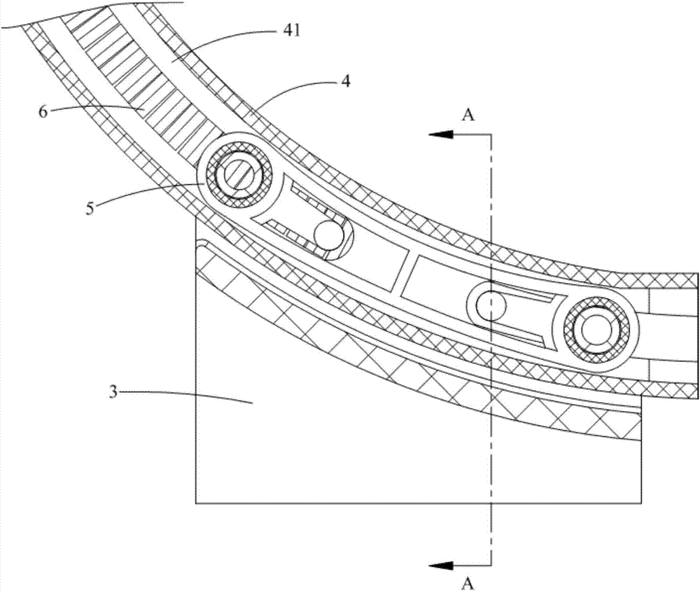
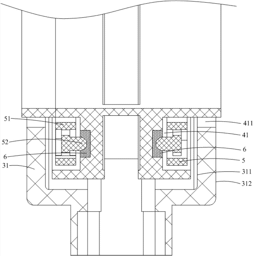
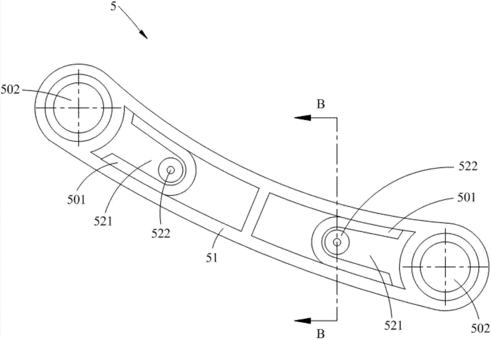
[0047] Such as Figure 1-8 As shown, the fan provided by Embodiment 1 of the present invention includes a fan head assembly 1, a base assembly 2, and a bracket 3 connected between the fan head assembly 1 and the base assembly 2. The back of the fan head assembly 1 facing the bracket 3 is provided with The arc track 4 and the end of the bracket 3 facing the fan head assembly 1 are provided with a slider 5 slidably installed in the arc track 4 .
[0048] Specifically, the fan head assembly 1 is mainly used to realize the blowing function of the fan; the base assembly 2 is mainly used to realize the placement of the fan in an application; the bracket 3 is mainly used to connect the fan head assembly 1 and the base assembly 2 . In the fan provided in this embodiment, an arc track 4 is provided on the back of the fan head assembly 1, and a slider 5 slidably installed in the arc track 4 is provided at the end of the bracket 3, so that the arc track 4 and the slider 5. After being a...
Embodiment 2
[0064] The main difference between the fan provided in this embodiment and the first embodiment is that the installation positions of the sliders 5 on the bracket 3 are different, specifically reflected in: Figure 1-8 As shown, in the first embodiment, each slide block 5 is symmetrically arranged on two opposite inner sides of the bracket 3 along the width direction of the bracket 3; Figure 9-10 As shown, in this embodiment, the sliders 5 are arranged symmetrically on two opposite outer sides of the bracket 3 along the width direction of the bracket 3 . By adopting the installation method of each slider 5 in this embodiment, the bracket 3 can also support the fan head assembly 1 from the left and right sides, which can also be beneficial to ensure the stability of the support of the bracket 3 to the fan head assembly 1; it is only different from the embodiment In comparison, on the premise that the width of the arc track 4 is equal, the width of the support 3 in this embodim...
Embodiment 3
[0071] The main difference between the fan provided in this embodiment and Embodiment 1 and Embodiment 2 is that the number of sliders 5 is set differently, which is specifically reflected in: Figure 1-10 As shown, in Embodiment 1 and Embodiment 2, the number of sliders 5 is an even number greater than or equal to two, and each slider 5 is symmetrically arranged on two opposite sides of the bracket 3 along the width direction of the bracket 3; And as Figure 11-13 As shown, in this embodiment, one slider 5 is provided, and the slider 5 is arranged on the top of the bracket 3 along the height direction of the bracket 3 . In order to ensure the stability of the bracket 3 supporting the fan head assembly 1, the width of the slider 5 extending along the width direction of the bracket 3 in this embodiment needs to be designed to be larger than the width of the slider 5 in the first and second embodiments. In this way, the cost of the slider 5 in this embodiment is slightly higher...
PUM
 Abstract
Description
Claims
Application Information
 - R&D
- Intellectual Property
- Life Sciences
- Materials
- Tech Scout
- Unparalleled Data Quality
- Higher Quality Content
- 60% Fewer Hallucinations
Browse by: Latest US Patents, China's latest patents, Technical Efficacy Thesaurus, Application Domain, Technology Topic, Popular Technical Reports.
© 2025 PatSnap. All rights reserved.Legal|Privacy policy|Modern Slavery Act Transparency Statement|Sitemap|About US| Contact US: help@patsnap.com