Pollutant emission response unit-based control unit pollution load verification method

A pollution discharge and control unit technology, applied in data processing applications, instruments, calculations, etc., can solve the problems of inability to use uniform and effective data and difficult implementation, and achieve the effect of solving pollution load estimation

Active Publication Date: 2017-11-24
CHINESE RES ACAD OF ENVIRONMENTAL SCI
View PDF3 Cites 2 Cited by
  • Summary
  • Abstract
  • Description
  • Claims
  • Application Information

AI Technical Summary

Problems solved by technology

[0005] Since 2014, the Ministry of Environmental Protection has launched a water quality assessment management system based on control units, and local governments have gradually carried out the pr

Method used


Image

  • Pollutant emission response unit-based control unit pollution load verification method
  • Pollutant emission response unit-based control unit pollution load verification method
  • Pollutant emission response unit-based control unit pollution load verification method

Examples


Embodiment Construction

[0030] Combine below Figure 1 to Figure 5 In detail, the pollution load verification method of the control unit based on the pollution discharge response unit of the present invention mainly uses land use data and existing statistical data to verify the pollution load of the control unit, so as to effectively support the water quality target management of the control unit.

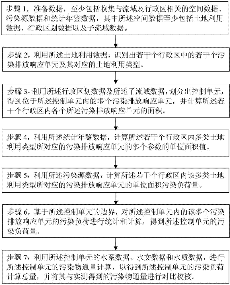
[0031] Such as figure 1 As shown, a preferred control unit pollution load verification method based on the pollution emission response unit of the present invention mainly includes:

[0032] Step 1, preparing data, including at least collecting spatial data, pollution source data, and statistical yearbook data related to watersheds and administrative regions, wherein the spatial data includes at least land use data, administrative division data, and sub-basin data;

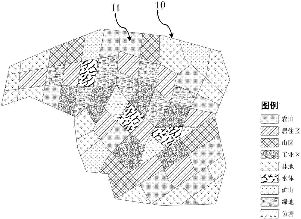
[0033] Step 2, using the land use data to identify several pollution discharge response units and their corresponding land use types in sev...


PUM


Abstract

The invention relates to a pollutant emission response unit-based control unit pollution load verification method. The method includes the following steps that: step 1, data are prepared; step 2, a plurality of pollution emission response units in a plurality of administrative districts and land use types corresponding to the plurality of pollution emission response units are identified; step 3, a control unit is defined through division, a plurality of pollutant emission response units located in the control unit are obtained, and the area of each of the pollutant emission response units in the plurality of administrative districts is calculated; step 4, the unit area values of a plurality of parameters of pollution emission response units corresponding to the plurality of land use types in the plurality of administrative districts are calculated; step 5, the unit area pollution load capacities of the pollutant emission response units corresponding to the plurality of land use types in the plurality of administrative districts are calculated; and step 6, the pollution load of the plurality of pollution emission response units in the control unit is put into statistics and is calculated according to the boundary of the control unit, so that the pollution load capacity of the control unit is obtained.

Description

technical field [0001] The invention belongs to the technical field of water environment protection and environmental management, in particular to the technical field of control unit water quality target management. Background technique [0002] Control unit water quality target management technology is an important supporting technology for the transformation of my country's environmental management from the total target management model to environmental quality management. Adhering to the management mode of "zoning, classification, grading, and stages", with the core of ensuring the health of the water ecosystem in the basin and improving the ability to control and manage water environmental pollution and decision-making support, and considering the level of social and economic development, implement the management of pollutant discharge permits for control units, support my country's environmental management progress. [0003] Basin control unit is the basic unit of water...

Claims


Application Information

Patent Timeline
IPC IPC(8): G06Q50/26
CPCG06Q50/26
Inventor 乔飞雷坤安立会李子成周刚邓义祥徐香勤
Owner CHINESE RES ACAD OF ENVIRONMENTAL SCI
Why Eureka
Try Eureka