A commodity carrying out device of a vending machine

A technology for vending machines, merchandise, applied in the direction of coinless or similar appliances, coin-operated devices for dispensing discrete items, coin-operated devices for dispensing discrete items, etc.

Active Publication Date: 2017-11-24
FUJI ELECTRIC CO LTD +1
View PDF10 Cites 5 Cited by
  • Summary
  • Abstract
  • Description
  • Claims
  • Application Information

AI Technical Summary

Problems solved by technology

[0003] Here, in the above-mentioned patent document 1, there is no clear description of the product delivery device, but this type of product delivery device includes: a first stopper member, which can enter and exit the product storage passage, and is arranged to be able to maintain the first sales order. The product (the product at the end, also referred to as the sale product) protrudes between the protruding position of the product storage passage and the retreat position that retreats from the product storage passage in a manner that releases the holding of the above-mentioned sales product; the second stopper member , which can enter and exit the commodity storage passage, and is set so as to be able to keep the commodity in the second selling order (commodity next to the rearmost commodity, also referred to as the next The way of selling

Method used


Image

  • A commodity carrying out device of a vending machine
  • A commodity carrying out device of a vending machine
  • A commodity carrying out device of a vending machine

Examples


Embodiment approach 1

[0129] Figure 1 to Figure 2 2 is the product delivery device of the automatic vending machine according to Embodiment 1 of the present invention.

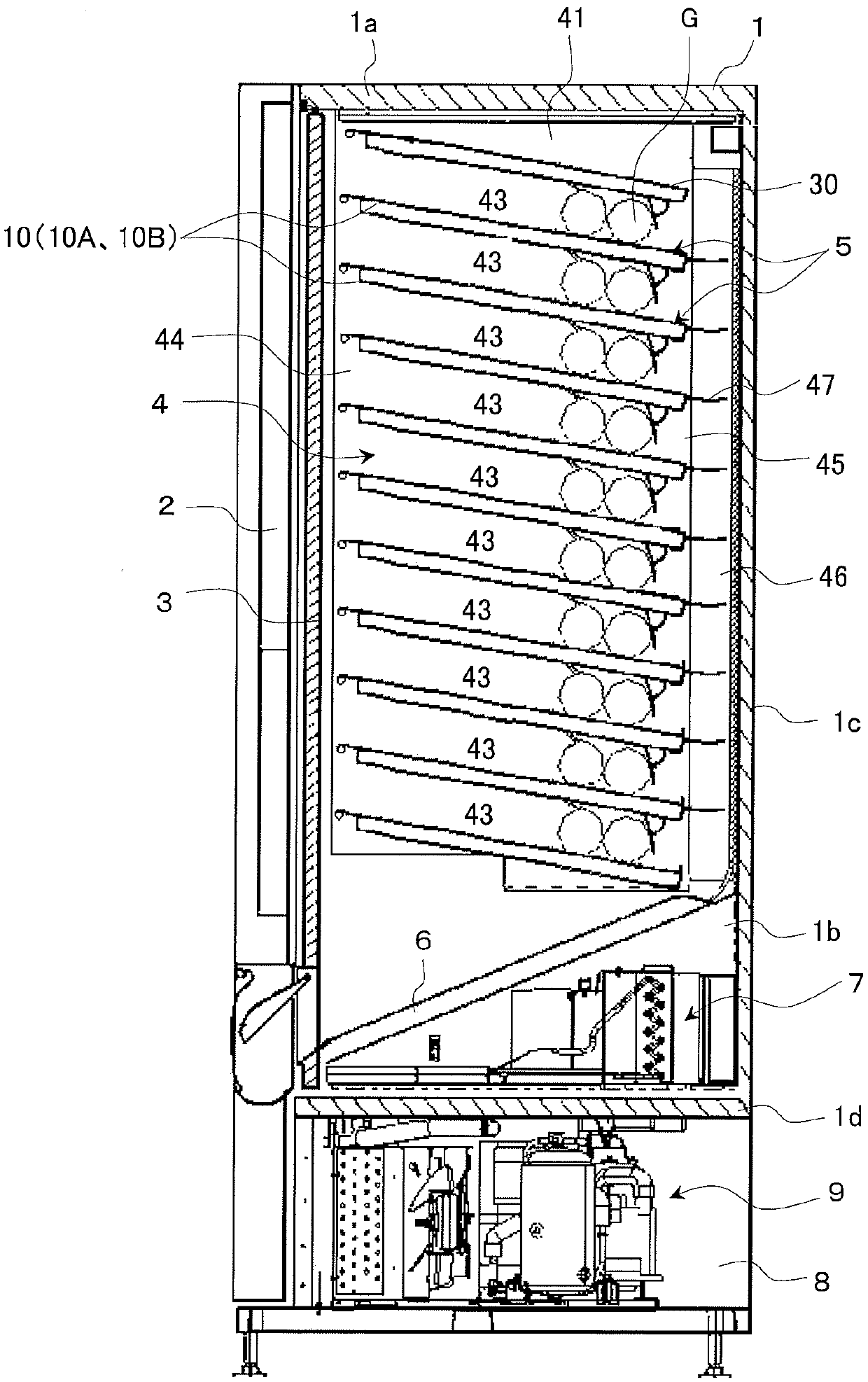
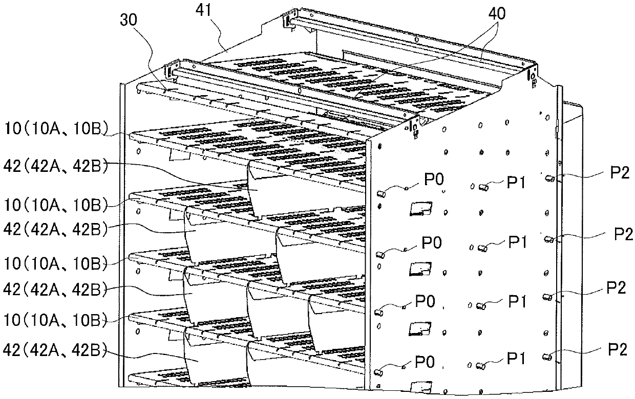
[0130] figure 1 It is a schematic side view of a vending machine that sells canned beverages and PET bottled beverages as an example of the automatic vending machine that is the object of the present invention, figure 2 It is viewed from the upper right obliquely figure 1The product storage shelf of , an exploded perspective view showing the main parts of the top product storage shelf. In addition, "left and right" means left and right when viewed from the front of the automatic vending machine.

[0131] Such as figure 1 As shown, this automatic vending machine includes: a main body cabinet 1 formed as a heat-insulating box with an open front, and an outer door 2 supported on the front of the main body cabinet 1 in an openable and closable manner. The front of the product storage compartment of the main body cabinet 1 is ...

Embodiment approach 2

[0200] figure 1 , figure 2 , Figure 11 , Figure 12 , Figure 18 , Figure 20 and Figure 23 ~ Figure 3 Numeral 6 denotes a product delivery device of the automatic vending machine according to Embodiment 2 of the present invention.

[0201] Merchandise storage shelf 10A, such as Figure 23 As shown, flanges 11, 11 bent downward from the left and right side edges of the rectangular plate surface are formed for reinforcement. At the front end of the commodity storage shelf 10, a hollow portion 12 bent into a hollow cylindrical shape (curled shape) is formed. The front portion of the flanges 11, 11 is notched to form a pin insertion portion 11a, and the flange 11 is substantially in the middle and at the rear end to form arc-shaped pin engaging portions 11b, 11c by notching. The pin insertion portions 11a and the pin engagement portions 11b, 11c provided on the flanges 11, 11 and the pin members P0 to P2 (refer to figure 2 ) to face each other, the product storage she...

Embodiment approach 3

[0282] figure 1 , figure 2 , Figure 18 and Figure 37 ~ Figure 59 It is a product dispensing device for an automatic vending machine according to Embodiment 3 of the present invention.

[0283] Commodity storage shelf 10B, such as Figure 37 As shown, flanges 11, 11 bent downward from the left and right side edges of the rectangular plate surface are formed for reinforcement. A hollow portion 12 bent into a hollow cylindrical shape (curled shape) is formed at the front end of the product storage shelf 10B. The front portion of the flanges 11, 11 is notched to form a pin insertion portion 11a, and the flange 11 is substantially in the middle and at the rear end to form arc-shaped pin engaging portions 11b, 11c by notching. The pin insertion portions 11a and the pin engagement portions 11b, 11c provided on the flanges 11, 11 and the pin members P0 to P2 (refer to figure 2 ) to face each other, the product storage shelf 10 is arranged so that the product storage shelf 1...


PUM


Abstract

The present invention provides a product dispensing device for a vending machine which has a degree of freedom in setting a product column and stably stores the product in the product storage passage and minimizes a dead band to elongate the effective length of the product storage passage, Comprising: Two sets of discharge mechanism part which the drive discharge mechanism provided with the connection mechanism and the driven discharge mechanism provided with the connection mechanism which are divided | segmented in the longitudinal direction of a product are arranged in a line, The drive discharge | emission which drives these 2 sets of discharge mechanism part And a mechanism for connecting the drive and discharge mechanisms of the two sets of discharge mechanism units and the adjacent connection mechanism of the driven discharge mechanism to each other and connecting the adjacent connection mechanisms of the two sets of driven discharge mechanisms to each other The movable connecting member selectively cuts (clears) the movable connecting member by the partition member on which the product bar is placed, thereby dividing the discharge mechanism portion into the width suitable for the product bar.

Description

technical field [0001] The present invention relates to a product delivery device for an automatic vending machine, which includes a product storage rack, and the product storage rack is provided with a multi-layer product storage shelf in the vertical direction. The product storage path in which individual products are stored side by side in a row in the front-rear direction is used to deliver the products stored in the product storage path one by one by the product delivery device arranged on the rear end side of the product storage shelf. Background technique [0002] This type of automatic vending machine includes a product storage rack in the warehouse of the main body casing. The product storage rack is provided with multi-layer product storage shelves in the up and down direction. Product storage channels (also called product columns) that are arranged in a row in the direction of storage. The product storage shelf disposed on the above-mentioned product storage rack...

Claims


Application Information

Patent Timeline
IPC IPC(8): G07F11/28G07F11/06
CPCG07F11/28G07F11/62
Inventor 岩子努福田胜彦
Owner FUJI ELECTRIC CO LTD
Why Eureka
Try Eureka