U beam prefabrication cast-in-place design construction method

A construction method and cast-in-place technology, applied in bridge construction, bridges, bridge materials, etc., can solve the problems of low original linear elevation of existing lines, low technical and economic cost-effectiveness, and high construction clearance requirements. The cast-in-place operation time is short, which is beneficial to the construction quality.

Active Publication Date: 2017-11-28
CCCC SECOND HARBOR ENG
View PDF8 Cites 2 Cited by
  • Summary
  • Abstract
  • Description
  • Claims
  • Application Information

AI Technical Summary

Problems solved by technology

However, this design and construction method is suitable for the situation where the traffic under the bridge can be closed or partially closed, the clearance requirement under the bridge is not high, and the construction period is not tight. However, the traffic under the bridge cannot be closed, the construction clearance requirement is high, and the construction period In a tense situation, the traditional design and construction methods will show corresponding shortcomings; at the sa

Method used


Image

  • U beam prefabrication cast-in-place design construction method
  • U beam prefabrication cast-in-place design construction method
  • U beam prefabrication cast-in-place design construction method

Examples


Embodiment Construction

[0022] In order to make the objectives, technical solutions, and advantages of the present invention clearer, the following further describes the present invention in detail with reference to the accompanying drawings and embodiments. It should be understood that the specific embodiments described here are only used to explain the present invention, but not to limit the present invention.

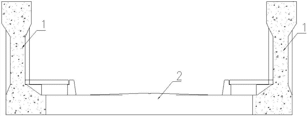
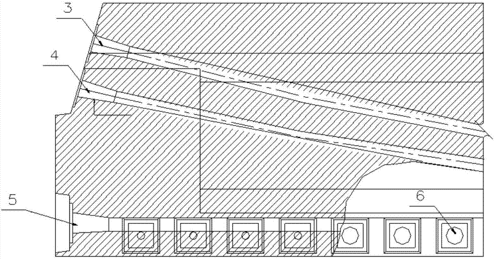
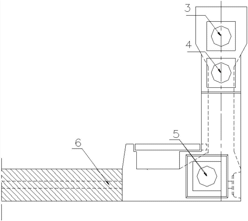
[0023] The technical solution adopted by the present invention to solve its technical problems is: the traditional U-beam structure is reasonably divided into two parts: the web (that is, the vertical web part) and the bottom (that is, the horizontal bottom part). , And design them separately. For the web design, the divided web is an "I" beam structure, and a single web has 3 prestressed steel strands in the longitudinal direction (≥3 prestressed steel strands can also be used as required). The design intent is that the 3 beams of prestress need to be stretched at one time to bear the beam l...


PUM


Abstract

The invention discloses a U beam prefabrication cast-in-place design construction method. The method comprises the steps that a U beam is integrally designed and divided into a vertical web part and a horizontal bottom plate part along the cross section of the U beam; after pouring of the vertical web part and middle and bottom prestressing tendon stretching and anchor sealing are finished, the vertical web part is hoisted to the position above a bridge pier and is fixed in the longitudinal direction of a bridge; the vertical web part on the bridge pier is utilized as a foundation for arrangement of a hanging frame and a bottom die, and field pouring of the horizontal bottom plate part is finished; and finally, a top longitudinal prestressing tendon and a bottom plate transverse prestressing tendon of a vertical web are stretched, and anchor sealing is conducted. The U beam prefabrication cast-in-place design construction method effectively solves the problems that underbridge traffic cannot be closed, the clearance requirement is high, and construction time is tense are effectively solved; the construction quality is guaranteed, and in the aspect of construction measures, economization is further achieved compared with an original traditional design construction method; and the construction period is short, and the construction time is short.

Description

Technical field [0001] The invention relates to a U-beam pouring design and construction method, which belongs to the technical field of traffic engineering bridges, and specifically relates to a U-beam precast cast-in-situ design and construction method for situations where traffic under the bridge cannot be closed, construction clearance requirements are high, and construction period is tight . Background technique [0002] In some bridges and railway construction double-track projects in the existing technology, some simply supported post-tensioned U-beam bridges are 2.6m high, 6.8m wide, 25m wide, 350t heavy, and across the highway. The traditional design is a one-time existing Pouring molding, traditional construction adopts full house bracket or steel pipe less bracket method for one-time cast-in-place construction. However, this design and construction method is suitable for under-bridge construction that can close or partially close traffic, under-bridge clearance requir...

Claims


Application Information

Patent Timeline
IPC IPC(8): E01D21/00E01D101/28E01D2/00
CPCE01D2/00E01D21/00E01D2101/28
Inventor 李文俊吴立柱易黎明李亚宋克坤张波裴国强陈为民章金飞邵明
Owner CCCC SECOND HARBOR ENG
Why Eureka
Try Eureka